Configurable parameters
Once downloaded in the Arduino board, the software set the default settings during the initial start.
These settings are appropriate for a configuration similar to mine (motors / ESCs / propellers / weight)
However, another configuration will probably require other parameters to be optimal.
For instance, if you want to use a larger multicopter for FPV.
The multicopter uses a closed controlled loop to ensure its stability and manoeuvrability.
Like most multirotors, it is a Proportional-Integral-Derivative (PID) regulator.
This controller is translated into software code lines in the Arduino and tries to correct the error calculated between a measurement at the controller output (measured by the gyros) and an input set point (position of the stick), using appropriate action to adjust the output of the process (command to motors).
PID controller involves three separate parameters: the term Proportional, the term Integral and the term Derivative. The variation of each of these parameters alters the effectiveness of the stabilization.
Applied to a multirotor, the coefficients of these parameters can be translated by their behaviour:
- Proportional coefficient: alone, it may achieve stabilization. This coefficient determines the importance of action on the engines in relation with the values measured by the gyroscopes. The higher the coefficient, the higher the tricopter seems more “rigid” versus angular deviation. If it is too low, the multicopter will appear soft and will be harder to keep steady. One can “feel” this setting by handling the tricopter and trying to change its orientation: the higher the parameter, the higher the opposition is important. In practice, this parameter must be set alone and increased up to be the limit for obtaining small oscillations. If too high, the system becomes unstable by amplifying the oscillations.
- Integral coefficient : this coefficient can increase the precision of the angular position. In practice, when the tricopter is disturbed and its angle changes, the term Integral remembers the disruption and apply a correction to the engines to get the right angle. We can see this term as an heading hold factor. Typically if you take handfuls the multicopter and try to force it into a position, the engines will continue for some time to counteract the action. Without this term, the opposition does not last as long. This way, the angular position can be steady and accurate even with irregular wind, or during ground effect. However, the increase of this ratio often involves a reaction speed decrease and a decrease of the Proportional coefficient as a consequence. Compared to the conventional PID algorithm, I decided to cancel this term in the presence of strong angular variations. This strategy allows a safer behaviour in case of looping or hard shaking.
- Derivative coefficient: this coefficient allows the tricopter to reach more quickly the requested attitude. In practice it will amplify the reaction speed of the system, and in certain cases an increase of the Proportional term. By cons, this parameters induces more noise.
By default, at the first startup, the tricopter is initialized with coefficient values that should be quite ok.
The multicopter uses 3 PID loops with their own P I DÂ coefficients, one per axis.
There are 2 ways to modify the values:
- The use of a specific combination of stick movements allows a sequential reconfiguration of these parameters with the help of a small LCD display. With this method, it is possible to quickly reconfigure the settings on the field, without even having to turn off the tricopter.
To see the modified values, a small LCD screen can be connected.
http://www.sparkfun.com/commerce/product_info.php?products_id=9394
The LCD is not necessary when you know (and memorize) exactly what you are doing (advanced users only)
- With a GUI running on a computer and a conventional USB connection between the multicopter and the computer.
Configuration via LCD
Start the LCD configuration mode
Tilt the yaw stick right + tilt the pitch stick forward.
This initializes the LCD if present, the LED flashes and the first parameter P is then ready to be configured.
Parameter selection
In setup mode, tilt the pitch stick back.
The selected parameter then changed sequentially and the LED blinks each time a new parameter is pointed.
The choice of parameter is indicated on the LCD on the first line.
Change the value of one parameter
In setup mode, tilt the roll stick right (increment) or left (decrement).
For the P parameter: the variation is in steps of 0.1, with a minimum value set to 0.
For the I parameter: the variation is in steps of 0.005, with a minimum value set to 0.
For the D parameter: the variation is in steps of 1, with a maximum value set to 0.
At each change the LED blinks
If we “count” operations, we can know the value of the parameter settings without LCD connected..
But we can quickly be lost if we made too many changes.
End of configuration mode
Tilt the yaw stick left + tilt the pitch stick forward.
The LED blinks again and tricopter returns in a state ready to fly.
(Note this video is not up to date, but the principle is identical)
Configuration via GUI
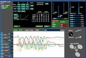
The GUI is a java program that can run on any PC windows/linux/mac computer.
The Arduino must be connected via an USB cable to the computer to use it.
Alternatively, it is possible to use a wireless transmission via bluetooth as data are transported over a simple serial port.
(not documented, but some managed to do it)
GUI launch procedure:
1) You must connect the arduino board to your PC via the USB connection (the same used to inject the software via Arduino IDE)
2) Once it’s done, you can launch the GUI, and then select the good PORT COM (the same used by arduino IDE).
3) Once it’s done, you have to wait some seconds to let the arduino boot and run the soft. (wait for the LED blink)
4) once the status led is OK (it should blink ans stays off), you can press the START button to see the evolution of values.
5) you must READ the current parameters in the Arduino before configuring it. Default values are set at the beginning.
The default values can be reset by uploading an old version and then the last version.
Parameter explanation
RC rate and RC expo
RC rate: defines the sensibility of the multicopter for PITCH and ROLL RC stick. If you feel your multi too reactive, decrease it. If you want to improve its responsiveness, increase this parameter.
RC expo: defines a smoother zone at the center of PITC and ROLL RC stick. With this function, it’s possible to have both a good precision and a good amplitude.
0 = no expo
1 = full expo
If you don’t understand really those parameters, I encourage you to read your TX documentation, as those functions are also generally suported by the TX.
It’s better to support them directly in multiwii because the resolution is better this way.
P and I Level
![]()
Defines the acc influence in stable mode only (this parameter has no effect if the stable mode is disable)
If the multi is not stable once activated, reduce P.
PITCH/ROLL/YAW PID and rate
For a very stable multicopter with a solid attitude, the PID settings must be set high. But if you want to do some acrobatics with these settings, the multi starts to wobble in fast translation or when you decide to shake it to much. One solution is to decrease the PID, but it is to the detriment of static stability.
So instead of implementing a switch between 2 PID settings, there are now 2 options in the GUI to define the way we should decrease PID, depending on ROLL/PITCH/YAW stick deviation
The two boxes on the right defines the rate of cancellation of the nominal PID (the one which is used on neutral ROLL/PITCH/YAW stick position) in relation with ROLL/STICK/YAW deviation. In fact only P and D parameters are impacted in the transformation. The purpose of this setting is not really to gain more stability, but to gain more maneuverability. 0 = soft rate (for FPV or beginners); 0.4 = soft acro ; 0.7 = fast acro ; 1 = insane rate
If you are not familiar with this, just keep the default values (0)
THROTTLE rate
This boxe defines the rate of cancellation of the nominal PID (the one which is used on neutral ROLL/PITCH stick position) in relation with Throttle stick.
The purpose of this curve is to gain more stability when you are in a situation to use more throttle than needed to just maintain a lift. This is typically the case in fast translation.
If you are not familiar with this, just keep the default values (0)
How to activate options

Depending on your configuration, you can easily activate/deactivate options via 2 switches on your RC TX.
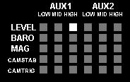
The 2 switches correspond to channel 5 (AUX1) and channel 6 (AUX2).
LEVEL is the autolevel feature (require an ACC)
BARO allows to keep a constant altitude once activated (require a barometer)
MAG allows to keep a perfect heading direction once activated (require a magnetometer)
CAMSTAB: if activated, the PITCH&ROLL servo output will follow the inclination of the multi (require an ACC + the code activation via #define statement)
CAMSTRIG: if activated, a servo output will trigger repetitively a sequence where we can define the duration on the HIGH/LOW position.
To activate a function, you must check the white box at the intersection of the required option (row) and at the switch state you want to enable (column).
It’s possible to make a complex mix.
If you want to force an option permanently, it’s possible to check all the white boxes, even without a RC channel connected.
(=> this way, you don’t need a 5 or 6 channels RC receiver)
Sensor detection/usage
On this screen, the left column resumes the detection of sensors.
The right column precises if the sensor is currently use or not (depending on the  checked options)
Stick combination summary
http://multiwii.googlecode.com/svn/branches/Hamburger/MultiWii-StickConfiguration-18_v0-57721.pdf
Source Code & GUI
The code source is stored on a google code repository:
http://code.google.com/p/multiwii/source/browse/#svn%2Ftags
You just have to select and download the last zip version.
One directory contains the Arduino sketch, and the other contains the GUI.
This code won’t compile, you have to uncomment first one of this two lines depending of your ESC type:
//#define MINTHROTTLE 1310 // for Turnigy Plush ESCs 10A //#define MINTHROTTLE 1120 // for Super Simple ESCs 10A
There are several option that can be adjusted (via #define word) directly in the sketch before uploading it on the Arduino.
The type of the multicopter (tri/quad/hex) is one of them.
Thanks to numerous examples found on the Internet, I developed this app.
To my knowledge, there are some new and reusable parts (radio interface, LCD interface, the servo control).
I would like to share this code and spread it under the GPL licence so that it serves other, directly or indirectly in a tricopter or for other projects.
It’s thank to this approach that the open source community Arduino has developed so fast.
The limits of memory and power the Arduino used here are not reached, and the number of I/O remains large enough to integrate a lot of other sensors, magnetometer, accelerometers, GPS, altimeter, ultrasonic sensor, …
My initial goal here was to make a minimalist multicopter, acrobatic oriented.
The cost of a minimal board with 3 gyroscopes could be very low: $30-$40


