Basic setups
Arduino Pro Mini + Wii Motion Plus
Dimensions of the Wii Motion Plus are quite similar to Arduino Pro Mini card’s one.
This is useful for designing a small and homogeneous card.
The 2 PCBs are simply connected by four wires.
Wii Motion Plus extension is powered by the regulated 5V of the Arduino Pro Mini.
Digital PIN 12 of the Arduino is connected to VCC Wii Motion Plus.
This PIN is commuted just after the Arduino boot sequence in order to fiabilize the WMP initialization and in order to fast reboot the WMP in case of a blocking state.
(This power option is mandatory for some WMP which enter sometimes in a blocking state. It is still unexplained at the moment.)
The analog inputs A4 and A5 are connected via the I2C pins SDA and SCL.
(the photo describes the old way to power WMP via VCC and not PIN 12)
Arduino Pro Mini + Wii Motion Plus + Nunchuk
Note that it is not mandatory to use a Nunchuk to operate the Multicopter described in this article.
It is mandatory only if you want to have an autolevel feature.
The software recognizes automatically the presence of a nunchuk connected.
Only 4 wires need to be connected between the WMP and the NK.
The relative orientation of the 2 PCB must be respected.
The WMP is connected to the Arduino exactly as described above.
Advanced setups
MultiWii can now handle many more sensors than just the WMP or NK.
Other GYRO, other ACC can be used.
New possibilities are available with sensors that did not exist initially: magnetometer and  barometer.
The flying quality of the boards is exclusively due to its sensors, the way they are powered and the code they run.
In other words, boards will have exactly the same flying characteristics is they share the same specifications.
Standalone solution: Arduino board + sensors board
It’ possible to upgrade a basic setup by adding some sensors with breakout boards (Sparkfun has multiple references)
Or it’s possible to buy a complete sensor IMU to connect to an Arduino. (pro mini or mega boards)
This kind of IMU is clearly something to get for an advanced setup as everything is soldered on a very tiny PCB board.
Some Arduino board example:
Some IMUs example:
Integrated solution: Arduino+sensors on the same board
We can now find some FC boards compatible with multiwii software.
The sensors are soldered on the same PCB.
Some integrated boards example:
Shield or not shield ?
To connect the Arduino to the ESCs or servos, there are several choices:
1) It’s possible to do a direct connection between elements like shown in the pictures above (WMP or WMP+NK)
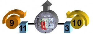
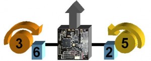
Example for a tricopter or a quad:
2) It’s possible to use a shield which is basically a passive PCB with convenient routed copper paths.
A shield for multiwii can be found now in several shop over the world.
Some shields example:
With a direct connection or a shield, the arduino PIN number is generally indicated and should be used for the setup of your choice.
In every case, The RC is connected as shown in the example for the tricopter.
Connecting Motors and Servos
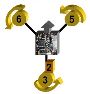
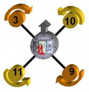
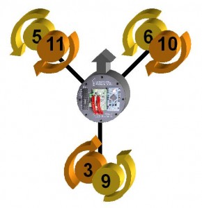
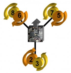
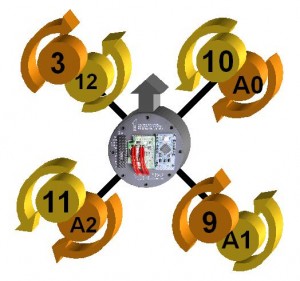
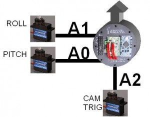
The table bellow indicates which PIN number should be used for a specific multirotor choice.
The Mega board on the pictures bellow is the Flyduino Mega.
Orientation of the card must be respected (blue arrow)
To build a powerful multicopter, it’s best to feed the controllers in a star delivery configuration from the battery with wires of the same section and same length. Otherwise, they might not be fed uniformly, especially in case of high amperage.
A simple 4-channel receiver (no mixing) can be used for a gyro-only multicopter. The code is robust enough to support all brands.
Connection diagrams
many thanks to Berkely 😉
more information on other possibilities on Berkely blog here: http://www.rcgroups.com/forums/showthread.php?t=1340771
and here:Â http://multiwii.googlecode.com/svn/trunk/Doc/Diagrams/


