Could you please test latest r90 with your UniLog?
regards,
ziss_dm
Hello! With r72, the MT3506 motor actually seems to run quite well, without losing timing (or recovering well, I can't tell )
r75: btw, you can use movw temp1, temp3, instead of the two movs, when the registers are in order. Also, there is a redundant sei near the top of update_timing.
Trying r84, startup seems much better, but I'm not quite sure why. Is that just the MSB change?
I can't start the HD on this BlueSeries 30A board because it keeps getting false timing and makes tones instead of turning,
Starting with 3 props on one motor doesn't work reliably and not at all unless I have at least 13V input voltage.
I'm surprised that you actually got it to work so well considering that there does not seem to be any alignment to PWM.
the spikes are still there. Is it possilbe that the filter is causing some "input lag"?
But looks like it also limiting the current (was 42 now 36).
The question is: Is it worth it?
Is it still screming?
funth1ngs wrote:I have timing problems (screams) on the first 3-4 fast throttle changes, but then they are gone until the ESC is restarted. Is it possible to make a special version which writes the working timing values into the eeprom, then we can read the eeprom an use them as start values in the normal version?
EDIT: Looks like you changed time base.. So step response still the same ~500 msec?
I also have some resets when idle throttle is to low.
Code: Select all
;*************************
; Run settings           *
;*************************
#define    RPM_RUN_MIN_RPM     750 ; 3200
I have timing problems (screams) on the first 3-4 fast throttle changes, but then they are gone until the ESC is restarted. Is it possible to make a special version which writes the working timing values into the eeprom, then we can read the eeprom an use them as start values in the normal version?
Code: Select all
750 - is too low. Remeber, this is electrical RPM.Code: Select all
RPM_START_MIN_RPMCode: Select all
RPM_RUN_MIN_RPMCode: Select all
ENOUGH_GOODIESCode: Select all
RPM_STEP_INITIAL, RPM_STEP_MAXCode: Select all
PWR_CURVE_POINT- What version should I use? Latest from svn ? O maybe hex file attached to topic?
Code: Select all
SET AS="%ProgramFiles%\Atmel\AVR Tools\AvrAssembler2\avrasm2.exe"
SET AS_FLAGS= -I "%ProgramFiles%\Atmel\AVR Tools\AvrAssembler2\AppNotes"
- For mystery 20A should I remove capacitors ? or this is not required?
Maybe this is not important but I'm going to use this ESC with KDA 20-22L (924kv).
Oh... , so electrical rpm = (motor rpm * stator poles) / 2? Is this correct?
Code: Select all
PWR_CURVE_POINT(01, 3500, 25)
PWR_CURVE_POINT(02, 7000, 50)
funth1ngs wrote:- Build this flash adapter. I think we don't need the pullup/pulldown stuff (R2) because we don't connect more than one ESC at a time. As I understand it, it also depends on the resistor which is connected to PPM_IN on the ESC. In my case it's a 220R, so I don't need a pullup/pulldown.
So if I want to program only one ESC in the same time I need to only put resistor R1 between TTL-RX and TX? And there is no information about resistor values for Mystery 20A but this should be something about 4,7k-10k ?
So like I described I probably don't need to R2 but you suggest 2k2 as R1. I will try other values if will have problems. But last question...
I'm not AVR guru so I need to write this value to fuses:
avrdude -p m8 .....-U hfuse:w:0xD8:m
But also tried to use method described above with bootloader but without success - can't connect from PC program. But I don't remove any capacitor because can find correct. Could you make describe with one did you remove ?
Almost..rpm = (motor rpm * rotor poles) / 2.
ENOUGH_GOODIES - number of successful electrical rotations before checking RPM.
RPM_START_MIN_RPM - minimal RPM for transition to run
RPM_STEP_INITIAL, RPM_STEP_MAX - initially when there no back EMF, it starts commutation with RPM_STEP_INITIAL speed and accelerates up to RPM_STEP_MAX. For a good start you need to provide enough power to rotate motor (with load) at least at RPM_STEP_INITIAL and motor should be able to produce detectable back EMF somewhere inside this range.
RPM_RUN_MIN_RPM - below this RPM it exits from run mode. Currently we have 2 cases:
- if current power is lower than PCT_PWR_MAX_STARTUP it goes to startup
- if higher - reset
Code: Select all
PWR_CURVE_POINT(01, 3500, 25)
PWR_CURVE_POINT(02, 7000, 50)
Basically it says that below 3500 limit power to 25% and below 7000 limit power to 50%. It is done to prevent overcurrent in case you put WOT at low rpm.
Code: Select all
PWR_CURVE_POINT(01, 6300, 25)
PWR_CURVE_POINT(02, 8400, 50)

#define    RPM_STEP_INITIAL    90
#define    RPM_STEP_MAX        250
#define    PCT_PWR_STARTUP     12
#define    PCT_PWR_MAX_STARTUP 16
#define    RPM_START_MIN_RPM   5600 ; 4200
#define    ENOUGH_GOODIES      20
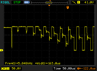
#define RPM_RUN_MIN_RPM 4200 ; 3200Simon wrote:Here are some from when I tried to do a differential measurement at the
ACO AVR pins by doing math on my two-channel scope:
...
I'm not sure how accurate the timing/spike behaviour is on both channels,
though, so a real differential probe would probably be better. However,
you can clearly see the commutation steps (every 1ms in the not full
speed case), and the noise it has to deal with, even on this AfroESC
board with filtering capacitors. That is modified code that had no delay
after zero cross, so it goes immediately to the next commutation step
after detecting the crossing. The zero crossing is when the purple line
crosses its zero point. (The noise on the purple line only cancels out
every 1 of 3 commutation steps, so ignore the rest.)
sim wrote:I didn't realize you saw problems even with slow throttle increases. Does this also happen with my tree? I thought it was only a fast response change problem. This is with a 14" APC prop?
sim wrote:It's possible that the motor is just saturating due to too much current.
ziss_dm wrote:I was just thinking: Maybe we are looking in wrong direction? Maybe something wrong with this "virtual" charge pump on this boards?
Code: Select all
                ror     temp1
.endif
                cpi     temp1, POWER_RANGE - 1 - 15
                brcs    eval_rc_p10
                ldi     temp1, POWER_RANGE - 1 - 15
eval_rc_p10:
mov ZH, temp1Code: Select all
run_to_start:   sbr     flags2, (1<<STARTUP)
                cpi     ZH, PWR_PCT_TO_VAL(PCT_PWR_MAX_STARTUP)
                ; brcs    run_to_start_2
                ; rjmp    restart_control
run_to_start_2:
rjmp wait_for_power_onAll version have a huge problem with motor startup, motor shaking about 3-5s then start working normally - all version except this attached to post above. It works without any problems. So I think changes related with Mt motors is not good for other motors...
Code: Select all
#define    PCT_PWR_STARTUP     20
#define PCT_PWR_MAX_STARTUP 25Code: Select all
#define    RPM_STEP_INITIAL    70
#define RPM_STEP_MAX 250I have some question for Mystery 20A users. I had some crashes when testing this software (because testing to high PID values, and landing in a grass, on the wall etc but luckily didn't burn any mosfet, so did you guys burn anyone when you stop propellers ?
I limited MAX_THROTTLE to 185 steps
I noticed with resets disabled that the motor nearly stops for a very short time, then immediatly accelerates to full speed.
Code: Select all
#define    RPM_STEP_INITIAL    70
#define    RPM_STEP_MAX        250
ziss_dm wrote:@marbalon: Can you try the latest 0.11 tag? For my setups it is finally better or equal to the original one.
The latest versions should be quite safe. I'm doing stop tests from half throttle. The erly ones may or may not burn FET's, depends on luck.
funth1ngs wrote:Hi simon and ziss_dm,
...
This made me to open another ESC
...
Heiko.
But you are "loosing" 45W of power (according to the graphs), so maybe smaller prop is better?
I also noticed that you always start ramping from different RPM. Can you try to fix initial RPM to fixed value? Maybe we have some treshhold, after which it start resetting? Would be fun if it is 1200 RPM
BTW: How you generating input? Manually?
ziss_dm wrote:Can you try the latest 0.11 tag? For my setups it is finally better or equal to the original one.
I use an AVR development board with a poti and a self written software to generate a 400Hz PWM signal.
Code: Select all
PWR_CURVE_POINT(01, 3500, 25)
PWR_CURVE_POINT(02, 5600, 50)
ziss_dm wrote:Hi marbalon,
What motors/props are you using? And have you removed back EMF feedback capacitors?
And if you like experiments, you can try to adjust STRT_ZC_FILTER_DELAY in core\str_zc_filter.inc. I think, you can lower it little bit.
regards,
ziss_dm
marbalon wrote:Will try to tune STRT_ZC_FILTER_DELAY and will give you feedback when I get home.
ziss_dm wrote:And to generate step, you just rotate pot fast?
ziss_dm wrote:And it depends on idle rpm?
ziss_dm wrote:Can you try to LOWER the second power curve point?Code: Select all
PWR_CURVE_POINT(01, 3500, 25)
PWR_CURVE_POINT(02, 5600, 50)
The idea is:
- When you rotate pot, it can change fast but not immidiate, so motor can keep up and everythingis fine
- When RPM is low, the limiter limiting power to 50% and this is good, but than motor reaches treshhold RPM it can generate "step" change in power
funth1ngs wrote:If this will not fix your problems, try to remove the BEMF capacitors on one ESC as the next step. It's possible that your capacitators have a greater capacitance what affects BEMF meassurement in a negative way. And you can try to increase PCT_PWR_STARTUP and PCT_PWR_MAX_STARTUP even more.
marbalon wrote:You think about three caps on the top right side on this foto?
Can you try to LOWER the second power curve point?Code: Select all
PWR_CURVE_POINT(01, 3500, 25)
PWR_CURVE_POINT(02, 5600, 50)
The idea is:
- When you rotate pot, it can change fast but not immidiate, so motor can keep up and everythingis fine
- When RPM is low, the limiter limiting power to 50% and this is good, but than motor reaches treshhold RPM it can generate "step" change in power
In Rev 115, I have added support for "Complimentary" PWM (for n-fet boards, and it is disabled by default). It would be interesting to hear, how it performs on your setup.
Code: Select all
And it would be interesting to see acceleration/deceleration profiles, as it actively breaking.Code: Select all
5sec - 1300us
2sec - 1900us
2sec - 1400us
2sec - 1200usOK, but I don't know what it should do . At first looking, I didn't see any difference with or without COMP_PWM.
So, resets still happening?
Graphs are look cool: Looks like down slopes are shorter now and it is charging battery (which is strange).
ziss_dm wrote:Hi marbalon,
What motors/props are you using? And have you removed back EMF feedback capacitors?
And if you like experiments, you can try to adjust STRT_ZC_FILTER_DELAY in core\str_zc_filter.inc. I think, you can lower it little bit.
regards,
ziss_dm
ziss_dm wrote:Could you please try this version? The idea is simple: to have different ZC filter for low and high RPM. The question is: Is it worth to integrate it into main branch?
funth1ngs wrote:Hi Andrej,
here is the picture with the ISP pins. I have only one TY-P1, so I never used it in a copter.
Cheers,
Heiko
