Hi,
me and the entire Team already have the OSD samples gently sent from the manufactures.
Thanks to
Jani from
http://www.jdrones.com/ and
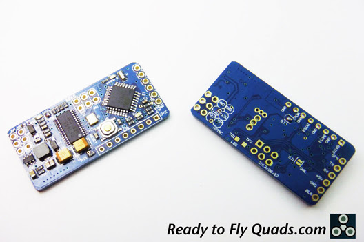
Paul Baxter from
http://www.readytoflyquads.com/These are from now on our supported and advised OSD´s.
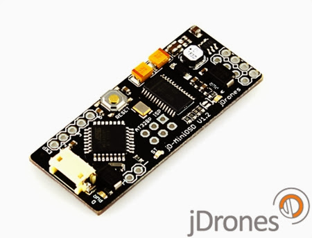
 JDronesv1.2 will be implemented on next release
 but I can say that small code changes are needed and you can start using it straight out of the box with KVTeam devr370.
I am using JDrones OSDv1.2 on my new FPV_SQUID without any code changes because I am
using MW Protocol to collect data (Voltage, RSSI and current sensing).
On next code release you will be able to use this OSD ADC´s and have full compatibility with this
awesome piece of hardware with the best quality control.
Now for the WiteSpy Minim OSD_v5,
I just got it in the mail and I will make tests during this weekend but all I can say at this time is that it have an
awesome price and built quality relation. Paul used the wiki Mods to make this hardware a
fully functional KVTeamOSD which means that it is supposed to work 100% straight out of the box, ADC inputs included. Also means no more soldering on the ATmel pins anymore.
I think we all should thank Paul for this OSD, awesome price and quality.
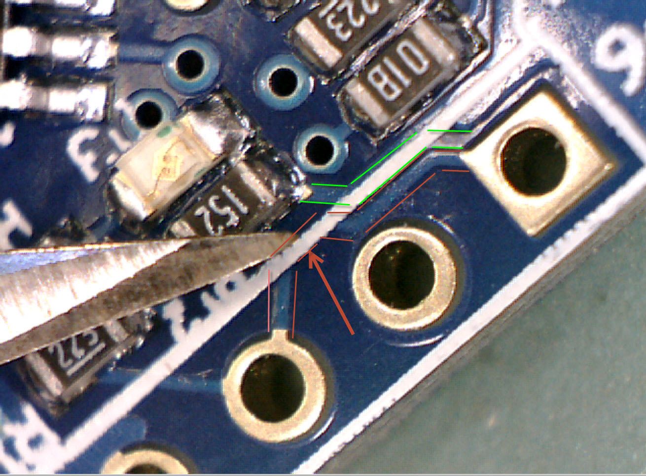
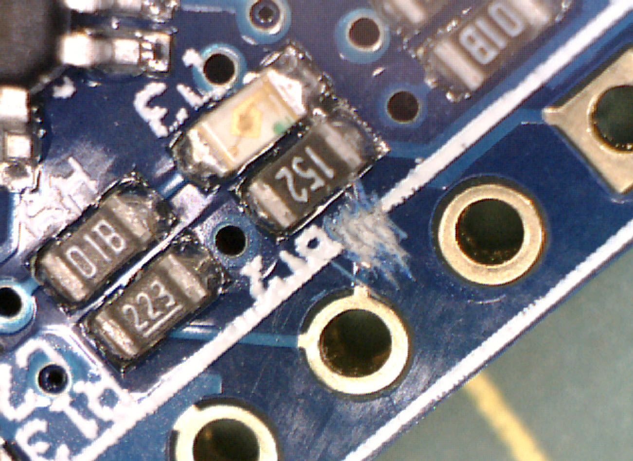
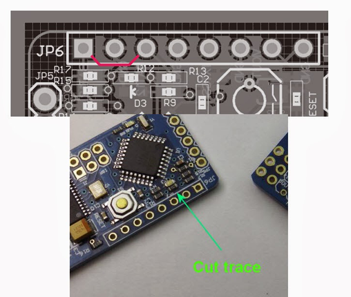
On this batch the only error I can notice at this time is with a simple trace that need to be cut, you can see it here on the following pic:
 EDIT:
EDIT: Full step guide to have a 100% working OSD.
I had sometime today so, I wanted to test this OSD immediately. Paul Baxter did in fact a wonderful work!Did the following steps on two fresh arrived units followed, I only advise you to use it like described below
in order to have it working at first try without any problems.
Step ZERO is to cut the above described trace or you will have a faulty OSD!First of all, as I said before I do not advise you to use 12v to power the video side, not only because you do not need it at all... but because it may cause several other problems/malfunctions, that is why they already arrive to your hands with the video side ready to be powered by your FC thru the serial port.
Now,
when you plug your OSD for the first time with live video output you will see that already have software on, that´s OK the part I don´t get is the is the default software itself


 The first step is to Clear the EEPROM, available on the Team´s code repository:
 The second step is to upload the most up to date KVTeam Software available on the repository:
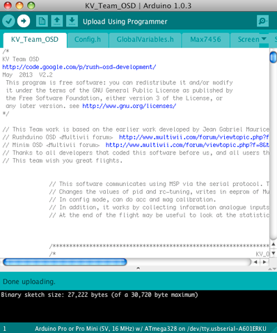 Third step is to upload your character map inside the GUI data folder:
 Done, 3 steps and you are ready to go out and have some serious fun
 with a fully 100% working WiteSpy OSD because you will see main screen when it boots up!
 Now for the ADC´s tuning part.
 Because electronic components have error tolerances, when using the ADC´s remember that from one input to another as for example battery one (which says Batt12

) and which also corresponds to the Video batt you probably will use (63) value on the Divider Ratio, and on the second battery (which also says Batt12

) and corresponds to Main Batt (just kidding, this is only a print error) you find yourself using (64 or other value) on it´s Divider Ratio to read exact same battery with accuracy (Use a good multimeter to get real voltage before tuning it).
The voltage dividers on this board can read up to 4s Batts and the RSSI pin up to 5v (remember to never go wrong on this or you will have to order another one, and of course Paul will appreciate your mistake
 I used all pin inputs with original code and no problem was found on both OSD´s fully tested.With this said I hope you follow carefully this instructions otherwise you may find unwanted problems and in truth you have nothing to blame on both, WiteSpy Hardware or Official KVTeam Software.
Just for the record and because this is as important as the described steps I use a SparkFun FTDI...
Have fun and fly hard but safe.
Cheers,
-KV
EDIT2: Same full revision will be made with JDrones OSD as soon as I got the courage to take it of my SQUID