Guys, maybe to centralize all questions regarding the I2C OLED (Crius or others) we can post here.
Let me start;
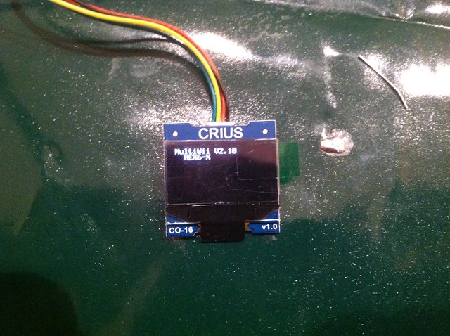
My OLED has the strange behaviour of only showing random pixels when connected during boot/power-on.
It does show the 'heartbeat'/pulse when the logo should be showing, but it doesn't show the logo.
When I connect the OLED on I2C after MWC has fully started, it shows logo nicely, but still no telemetry.
Video:
I2C OLED connected after MWC boot: http://dl.dropbox.com/u/9916558/I2C%20O ... 20boot.mp4
I2C OLED connected before MWC boot: http://dl.dropbox.com/u/9916558/I2C%20O ... 20boot.mp4
Defines:
#define LCD_CONF
#define OLED_I2C_128x64
#define LCD_TELEMETRY
#define LCD_TELEMETRY_AUTO "212232425262729"
I2C OLED thread
Re: I2C OLED thread
some thoughts
1. does it throw i2c errors with/without the oled attached upon startup?
2. with lcd.telemetry.auto you have to trigger the display once via the stick combo.
3. Alternately I use this setup with oleds now:
it will display the initial 'multiwii version xyz' & coptertype for 2 seconds, then automatically switch to display page 1.
Stepping to next page requires stick input.
1. does it throw i2c errors with/without the oled attached upon startup?
2. with lcd.telemetry.auto you have to trigger the display once via the stick combo.
3. Alternately I use this setup with oleds now:
Code: Select all
#define LCD_CONF

#define OLED_I2C_128x64
#define SUPPRESS_OLED_I2C_128x64LOGO

#define LCD_TELEMETRY
#define LCD_TELEMETRY_STEP "15240"
it will display the initial 'multiwii version xyz' & coptertype for 2 seconds, then automatically switch to display page 1.
Stepping to next page requires stick input.
Re: I2C OLED thread
same here, i have no i2c errors with/without oled upon startup.
connecting after boot of mwii and display works fine.
i have 2 oleds, one non crius and the crius oled, the dots just appear on the crius one, im try to catch a pic in lunch break
connecting after boot of mwii and display works fine.
i have 2 oleds, one non crius and the crius oled, the dots just appear on the crius one, im try to catch a pic in lunch break
Re: I2C OLED thread
Crius is also known to have firmware problems with their lcd. So maybe it is just that and you are out of luck.
Re: I2C OLED thread
Can you try with the other i2c speed?
Re: I2C OLED thread
You mean the speed/frequency at which sensors are polled?
Kept it standard for now, will try tomorrow and report back.
Kept it standard for now, will try tomorrow and report back.
-
Bergerac56
- Posts: 5
- Joined: Sun Nov 11, 2012 6:35 pm
Re: I2C OLED thread
I have two crius oled (co-16) and have the same problem with both. Random dots at startup unless it is connecetd after full initialisation of the oled. Could it be a problem with the init sequence?
Re: I2C OLED thread
Dunno.
I have two oleds from wide.hk both connected to simple crius boards on helis and both work ok.
I have two oleds from wide.hk both connected to simple crius boards on helis and both work ok.
-
Bergerac56
- Posts: 5
- Joined: Sun Nov 11, 2012 6:35 pm
Re: I2C OLED thread
your oled seems to be different than the crius one. The problem could come from a strange behavior of the Crius oled at startup (wrong reset,...)
Re: I2C OLED thread
crius has a reputation for wrecking firmwares of displays. They did it with serial LCD some time ago - thread here in forum somewhere.
Maybe they did it again with oled. I have no proof this is the case and/or how to repair/flash a working firmware.
But it seems a good guess as to what the reason for failure is.
So in future maybe best stay away from crius displays.
Maybe they did it again with oled. I have no proof this is the case and/or how to repair/flash a working firmware.
But it seems a good guess as to what the reason for failure is.
So in future maybe best stay away from crius displays.
Re: I2C OLED thread
Strange thing is (strange pixelation also happens with different I2C speed BTW!) that it does work fine when OLED is connected after FC has fully booted.
Also tried this on my Flyduino MEGA and sure enough, same shizzle, different board So that leads me to suspect some kind of I2C initialization error.
Maybe sensors are polled too soon for OLED to boot up? Dunno the code, but some geekish logic applied there
Also tried this on my Flyduino MEGA and sure enough, same shizzle, different board
Maybe sensors are polled too soon for OLED to boot up? Dunno the code, but some geekish logic applied there
Re: I2C OLED thread
Hopefully the right place to ask ,,
Have just received obe of these displays and wanted to check it out using a bare Arduino ( Considering the display for a non 'copter idea) with the supplied ( China dealer) Arduino sketch I get precisely nothing on the display , no sign of any life !! , Have any members managed to get a display using a bare Arduino Mega or Duemilanove ?
I've had a few i2c projects running on both boards and the results with the Crius board are almost as if the address ( 0x3c ) is wrong and the device is not replying to any commands
Art
Re: I2C OLED thread
Bergerac56 wrote:I have two crius oled (co-16) and have the same problem with both. Random dots at startup unless it is connecetd after full initialisation of the oled. Could it be a problem with the init sequence?
Hi, I have 2 of these screens and both give me the dots randomly on FC Boot. Tried connecting after and so far it works, first time into lcd config I get blank screen, come out I get the aborting exit, go in again I get all the config info but upside down??? reboot the FC and if the screen does not crash I get logo the right way up!
-
Bergerac56
- Posts: 5
- Joined: Sun Nov 11, 2012 6:35 pm
Re: I2C OLED thread
I GOT IT
After a lot of investigations it seemed that the reset/initialisation of the crius OLED co-16 v1.0 was the problem. I tried to solve this by modifying the software without result. As I did not find the "reset" pin to modify the way the oled was initializing, I used another way to stabilize the initialization process.
I just inserted a 100 ohm resistor in the positive line of the oled. This lowers very slightly the positive voltage and, combined with the capacitance on the PCboard, adds some filtering of the 5v. This permits a correct reset of the oled driver chip. The easiest way is to insert the resistor in the positive (red) wire but it is also possible to insert it on the pcb itself (needs very good eyes ).
Material: 1x 100 ohm 1/4 or 1/8 watt
a short piece of heat shrinkable tube to protect the resistor
Cut the red wire
Solder the resistor and protect it with the tube
And that's it.
Tried on several crius oled. Works perfectly
Enjoy
After a lot of investigations it seemed that the reset/initialisation of the crius OLED co-16 v1.0 was the problem. I tried to solve this by modifying the software without result. As I did not find the "reset" pin to modify the way the oled was initializing, I used another way to stabilize the initialization process.
I just inserted a 100 ohm resistor in the positive line of the oled. This lowers very slightly the positive voltage and, combined with the capacitance on the PCboard, adds some filtering of the 5v. This permits a correct reset of the oled driver chip. The easiest way is to insert the resistor in the positive (red) wire but it is also possible to insert it on the pcb itself (needs very good eyes
Material: 1x 100 ohm 1/4 or 1/8 watt
a short piece of heat shrinkable tube to protect the resistor
Cut the red wire
Solder the resistor and protect it with the tube
And that's it.
Tried on several crius oled. Works perfectly
Enjoy
Last edited by Bergerac56 on Thu Nov 29, 2012 6:55 pm, edited 1 time in total.
Re: I2C OLED thread
thumbs up - good catch!
Re: I2C OLED thread
Have the same issue. Have not fully tested yet, but the 30 pin connector of the OLED seems compatible with :
http://www.wide.hk/download/UG-2864HSWEG01.rar
Reset pin should be pin 14 of the 30 pin flat cable. seems to be connected to supply 3.3V.
http://www.wide.hk/download/UG-2864HSWEG01.rar
Reset pin should be pin 14 of the 30 pin flat cable. seems to be connected to supply 3.3V.
Re: I2C OLED thread
Using the Crius OLED: The board does not seem to have SDAin and SDAout connected to each other so you will not receive ACK from it.
For those fiddeling with your own code for bare Arduino you will have to make your code not care about ACK.
With this and the 100ohm trick I got the Crius OLED working rigth
Found this out by reading:
http://www.adafruit.com/datasheets/UG-2 ... 0guide.pdf
And watching the images of the board on EBAY eg.:
http://www.ebay.com/itm/CRIUS-CO-16-OLE ... 4609079ea4
-
Bergerac56
- Posts: 5
- Joined: Sun Nov 11, 2012 6:35 pm
Re: I2C OLED thread
Good suggestion.
But, in the specific case of the multiwii, connecting D1 and D2 together did not solve the problem for me. It was possible to differ the reset (with an RC circuit) but isolating the reset pin and addind the circuitry was more complex than simply adding the 100 ohm resistor
But, in the specific case of the multiwii, connecting D1 and D2 together did not solve the problem for me. It was possible to differ the reset (with an RC circuit) but isolating the reset pin and addind the circuitry was more complex than simply adding the 100 ohm resistor
-
jgarnham47
- Posts: 19
- Joined: Fri Nov 23, 2012 10:30 pm
Re: I2C OLED thread
To add to the story ...
The 100 ohm resistor trick didn't work for me. I also tried 470 ohms which made and it worse and 47 ohms. I attached a scope to the 5V supply and it rings, perhaps due to the inductor on the board, and when the display comes on the voltage dips and screws up the display again.
Like many I felt the reset pin is the issue. Most microprocessors and interface devices like their reset pin to be low on power up so they can reset internal registers on the rising edge of reset, the most common technique is to add an RC network to the pin. Because we are only using a 4 pin connector, the reset it tied to the supply and it becomes a race condition that may be dependance on the rate of rise of the supply. The evaluation kit mentioned above says 10ms low on the pin, which seems to long. Looking at something like the SSD1306 data sheet it says 3us is enough, page 27. http://www.solomon-systech.com/en/product/display-ic/oled-driver-controller/ssd1306/
I then used a scalpel, and 0.5mm soldering iron bit to isolate the reset pin of the display connector and lift it off the board. To this I added a 100nF cap and 100K resistor to form a standard RC circuit and ran the board again. To my surprise it just didn't work
Also in the data sheet above (second from last page) it gives the exact software configuration of the chip. I replicated this in the OLED init routine and followed it with a simple text message. Still didn't work consistently.
I have wasted a day and I am still at a loss, it's not the reset pin I suspected it was but it does appear to be a function of the power supply. Before I pull all the components off the board and start again from scratch, based on the discussion above does anybody else have another suggestion or two ??
Regards ... John
- Attachments
-
- Isolation of reset pin for testing
-
- RC Network shows delayed rise of reset pin (red) compared to 5V (Yellow)
-
- Series resistor causing ringing on 5V supply of board
Re: I2C OLED thread
RESET pin should be pin 14 of the 30 pin flat cable.
On the photo you can see that you have used the pin 13.
On the photo you can see that you have used the pin 13.
Re: I2C OLED thread
Is it positive these problems are limited to crius oleds?
I have 3 oleds from wide.hk direct or via ebay and never had any of the issues with powerup / init.
I have 3 oleds from wide.hk direct or via ebay and never had any of the issues with powerup / init.
-
jgarnham47
- Posts: 19
- Joined: Fri Nov 23, 2012 10:30 pm
Re: I2C OLED thread
Jantar wrote:RESET pin should be pin 14 of the 30 pin flat cable.
On the photo you can see that you have used the pin 13.
D'Oh, did I really get the wrong pin?!!
These things are too small even with a magnifying lamp.
Thanks very much, let me go try again ...
John
- Attachments
-
- Pin 13, D'Oh !!
-
jgarnham47
- Posts: 19
- Joined: Fri Nov 23, 2012 10:30 pm
Re: I2C OLED thread
YAY, FIXED IT  Simple schoolboy error before, using the right pin certainly helps!
  An RC network is all that is required.
I have several MultiWii boards but the Crius AIO Pro has constantly refused to work with the OLED display. I just tested it and it worked 20 times without fault
I have another board to double check and then I will post the best layout with photos later in the week (getting late here in UK).
For those that can't wait ... you just need something like a 100K resistor connected between 5V on the 4 pin connector and pin 14 on the display ribbon (once you have cut either side of the pin and lifted it off the board with a small iron, as shown above, with some insulating tape). Then a small capacitor between 10nF to 100nF connected between pin 14 and GND on the 4 pin connector.
Yes, it's that simple after all
Thank you Jantar for pointing out the obvious mistake.
Regards ... John
-
Bergerac56
- Posts: 5
- Joined: Sun Nov 11, 2012 6:35 pm
Re: I2C OLED thread
Héhéhé. I confirm, like said in my last post, that an RC network on the reset pin (14!) works. I did it too on one of my crius oled. I have today 4 crius oled at home and all 4 work with the 100 ohm. As I believe that the reset problem comes from a bad "raise" of the power supply of the multiwii controller used, the 100 ohm could work with some boards and not with others. If well equiped, the "reset" solution is certainly the most "universal"...
BTW I tested also with 2 Crius AIO V1.1 boards, with one HK SE V2 and one HK Lite V1 It worked with both "tricks"
BTW I tested also with 2 Crius AIO V1.1 boards, with one HK SE V2 and one HK Lite V1 It worked with both "tricks"
-
jgarnham47
- Posts: 19
- Joined: Fri Nov 23, 2012 10:30 pm
Re: I2C OLED thread
Just to finish off then ...
1) Start by using a scalpel and iron to isolate pin 14 (not 13!) and place some tape to prevent shorting.
2) You must pickup VDD from pin 9 for the resistor, this is the 3.3V supply used by the "core logic operation" (you can probably use the 5V supply but you will be over-driving the input and relying on a "catch" diode on the chips input). Then soldered a 100K resistor between pin 9 and 14.
3) Solder a 10nF capacitor (or 100nF) to pin 14 on the other side.
4) Connect the other-side of the capacitor to VSS (GND), Pin 30/31 is a convenient location.
Yes, it's tiny delicate work. If you are using wire ended components then I would probably just solder to the back of the 4 pin I2C connector and have a flying lead to pin 14.
At last, no more re-booting to see the display
Regards ... John
1) Start by using a scalpel and iron to isolate pin 14 (not 13!) and place some tape to prevent shorting.
2) You must pickup VDD from pin 9 for the resistor, this is the 3.3V supply used by the "core logic operation" (you can probably use the 5V supply but you will be over-driving the input and relying on a "catch" diode on the chips input). Then soldered a 100K resistor between pin 9 and 14.
3) Solder a 10nF capacitor (or 100nF) to pin 14 on the other side.
4) Connect the other-side of the capacitor to VSS (GND), Pin 30/31 is a convenient location.
Yes, it's tiny delicate work. If you are using wire ended components then I would probably just solder to the back of the 4 pin I2C connector and have a flying lead to pin 14.
Regards ... John
- Attachments
-
-
jgarnham47
- Posts: 19
- Joined: Fri Nov 23, 2012 10:30 pm
Re: I2C OLED thread
Hamburger wrote:Is it positive these problems are limited to crius oleds?
I have 3 oleds from wide.hk direct or via ebay and never had any of the issues with powerup / init.
Yes, I believe it is just the Crius version. I got mine from RCTimer.
The HK one looks to have a different set of components with larger capacitors.
The Paris version from MultiWiiCopter also seems to to work.
Regards ... John
Re: I2C OLED thread
Hi folks,
I didn't do enough research before I got the Crius CO-16 v1.0, so when I enabled the defines below, as you might have guessed, NOTHING happened on that screen. No light, no dots, nothing. It's plugged into the usual Crius SE.
Is this likely the 100ohm resistor + reset issue described above?
spag
Code used:
Code: Select all
#define LCD_CONF
#define OLED_I2C_128x64
#define SUPPRESS_OLED_I2C_128x64LOGO
#define LCD_TELEMETRY
#define LCD_TELEMETRY_STEP "015240"-
jgarnham47
- Posts: 19
- Joined: Fri Nov 23, 2012 10:30 pm
Re: I2C OLED thread
That set of defines should be okay. My two Crius displays always showed something, the usual fault is a series of random dots on the screen that gets brighter than dimmer a couple of times but will not clear to give the correct display text. Best check your I2C connections again, especially SDA and SCL.
Regards ... John
Regards ... John
Re: I2C OLED thread
jgarnham47 wrote:Hamburger wrote:Is it positive these problems are limited to crius oleds?
Yes, I believe it is just the Crius version. I got mine from RCTimer.
John,
thank you for clarifying. I will add a note to the wiki. Getting the oled crom another dealer sbould be the easiest route.
Re: I2C OLED thread
Hi all, I have this electronics:. It seems to be like Crius SE, but not sure. I have bought also a CRIUS CO-16 OLED 128x64 display, and I dont see anything when I connect to the board. May be the Multiwii 2.1 version inside doesnt have enable the corresponding "#defines".
That is not a problem for now, as I can connect to my drone over bluetooth an android phone. Later I will try to extract the .hex file inside my board (for backup pourpouse) and flash a compiled one with the OLED #defines...but this is a project.
What I am trying now, without success, is to get a simple "ack" from the OLED display, conected to an arduino Nano and nothing else. I use the I2C_scanner sketch from arduino playground page, no pullup resistors (as it is only one device), but I get only "no devices found" message. Pretty sure the wiring is OK...
For now, I dont have a logic analyzer to check more..
Any help?
Thanks in advance.
Re: I2C OLED thread
Hi,
I am currently setting up an AIOP board for a hex. I got one of the RCtimer OLEDs. I had the "random white dots problem" which was fixed by a single 100ohm resistor placed on the positive line in. My OLED now displays properly:
BUT, I dont seem to get the PID setting pages. And the battery voltage page is not reading properly (but I think I have to spend more time understanding the note on the config page about this) . I have, I think, 3 completely blank pages. I know one should be PID setting. Can someone tell me what setting I should have changed to be able to configure pids on the OLED? I can navigate through pages with full forward and full right roll stick input, but thats it.
I have:
#define LCD_CONF
#define LCD_CONF_AUX
#define OLED_I2C_128x64 // I2C LCD: OLED viewtopic.php?f=7&t=1350
#define LCD_TELEMETRY
#define LCD_TELEMETRY_STEP "0123456789" // must begin with 0
update: I notice that I get tons of I2c errors, and weird jumps in sensor values, if the OLED is left on some of the pages. ?????
update 2: I turned off vbatt and buzzer and stopped getting I2c errors. Then I stopped having the gps work. Couldnt figure out what was going on. Messed around with gps and settings for a bunch and THEN I somehow ended up in the pid editing page on the OLED. Is it just a stick combo to get into that? And if so what is it? once I exited out of there, my GPS came back. I am confused about what just happened.
-
jgarnham47
- Posts: 19
- Joined: Fri Nov 23, 2012 10:30 pm
Re: I2C OLED thread
Once you go into the PID menus system the processor stays there until you exit, so GPS reads will be off-line. If you are messing about in this area try adding the telemetry pages too. For instructions on Tx sticks check out this excellent page ... http://multiwii.googlecode.com/svn/branches/Hamburger/ I print them out and then laminated them and they stay in my Tx box for reference. LCD mode is shown. BTW thanks Hamburger
John
John
Re: I2C OLED thread
Oh, that was helpful. Thanks!
Re: I2C OLED thread
Hi again, anybody has got this OLED working with "Wire.h" (i2c) library from Arduino IDE? Or with the examples from WIDE.HK? I mean, in a separate scenary, not conected to MultiWii board, but to Arduino board...
Re: I2C OLED thread
I have one of the Crius boards and I get the top two lines on the display. I can change the text so I know I am communicating. I can't get the board to show anything else. I have tried different combinations of settings in the telemetry section but nothing seems to make any difference.
Any ideas?
Any ideas?
Re: I2C OLED thread
I just found the problem. I had to turn up the end points on my XMTR to get the board to recognize the commands.
Re: I2C OLED thread
fantastic thread thanks to all contributors, got my crius AIO and crius oled display working in 20 minutes after having "random snow flake dots" issue by using 100 ohm resistor (guess i was lucky not to have to use the capacitor.) the link to hamburgers stick commands downloads was a bonus!
Thanks everyone!
Thanks everyone!
-
dominicclifton
- Posts: 202
- Joined: Tue Feb 05, 2013 10:28 pm
Re: I2C OLED thread
ardufriki wrote:Hi again, anybody has got this OLED working with "Wire.h" (i2c) library from Arduino IDE? Or with the examples from WIDE.HK? I mean, in a separate scenary, not conected to MultiWii board, but to Arduino board...
Not with Wire.h, but i combined the MultiWii I2C code and the demo code and got it working just fine.
I uploaded the resulting code to github, it works with Arduino IDE 1.0.3.
https://github.com/hydra/UG2864HSWEG01
I am curious as to why it doesn't work with the Wire library, if you figure it out please let me know.
-
Hubbie0001
- Posts: 1
- Joined: Sun Feb 24, 2013 10:15 pm
Re: I2C OLED thread
My oled works with your coding. Thank you. Greate job. The reason off the failure with the wire-library is the missing acknowledge from the oled. It never send an ack. I have checked it with a 2-ray oscilloscope.
Re: I2C OLED thread
Hubbie0001 wrote:My oled works with your coding. Thank you. Greate job. The reason off the failure with the wire-library is the missing acknowledge from the oled. It never send an ack. I have checked it with a 2-ray oscilloscope.
wow, good info. Thanks.
-
szepnorbee
- Posts: 4
- Joined: Wed Dec 26, 2012 10:15 am
Re: I2C OLED thread
Anyone know how to apply this in the MW code? With this code works without resistor mod? Thanks
Re: I2C OLED thread
Checking deeply this in the datasheet, there are two wires coming from the sd1306 controller, but in this oled only the SDIN is connected. If you join SDOUT to SDIN it should send the ACK (not tested, dificult to solder...).
-
dominicclifton
- Posts: 202
- Joined: Tue Feb 05, 2013 10:28 pm
Re: I2C OLED thread
jgarnham47 wrote:Yes, it's tiny delicate work. If you are using wire ended components then I would probably just solder to the back of the 4 pin I2C connector and have a flying lead to pin 14.
Thanks for posting details of it, today I have fixed my OLED screen using wire ended components, and yes it really is a bit fiddly. Especially lifting pin 14 from the board. Still, it seems to work OK.
I used some silicon sealant/adhesive to hold the components in place too. Glue gun would probably be OK for that too but i don't have mine out here right now.
Here's a picture of my fix, not as clean as johns but it works just fine.

Re: I2C OLED thread
Greetings! I just received two Crius CO-16 OLED displays from RCTimer and have experienced the random dot problem.
Both units act the same on an AOIP controller from Hobby King. Rather than install a 100 ohm resistor in series with the
5 volt line I came up with a better and reliable solution. Apparently, applying 5 volts to the module and controller at the same time scrambles the display. I designed a circuit using a NE555 timer IC to create a turn on delay of the 5 volts applied to the CO-16. About a 1.5 second delay does the trick and works every time. I used pin 3 of the NE555 to power the display directly, as the 555 can source over 200 ma. Hope this info helps.
Re: I2C OLED thread
ardufriki wrote:Checking deeply this in the datasheet, there are two wires coming from the sd1306 controller, but in this oled only the SDIN is connected. If you join SDOUT to SDIN it should send the ACK (not tested, dificult to solder...).
Hi, I´ve got the ACK from the SSD1303 chip inside our OLED(seen in logic analyzer). Just joining pins 19 and 20 with a drop of soldering (no so hard to do). Now it works fine with Adafriut libraries and other Arduino skectches.
-
dominicclifton
- Posts: 202
- Joined: Tue Feb 05, 2013 10:28 pm
Re: I2C OLED thread
that's great ardufriki. i'll try that on mine when i get a chance.
-
jgarnham47
- Posts: 19
- Joined: Fri Nov 23, 2012 10:30 pm
Re: I2C OLED thread
dominicclifton wrote:Here's a picture of my fix, not as clean as johns but it works just fine.
Good effort Dominic, especially with wire-ended components
Regards ... John
Re: I2C OLED thread
Hello, I'm new here, and I come because buy 2 modules co-16 on ebay. for use with Arduino, but I can not print to display some character. Not if they are damaged or my code is wrong.
Download the sample from adafruit and http://www.wide.hk/download/i2c_OLED.rar
Any help me?
Hola , soy nuevo aqui, y vengo porque compre 2 modulos co-16 en ebay. para usarlos con Arduino, pero no logro que imprima en pantalla algun caracter. No se si estan dañados o mi codigo está mal.
http://www.ebay.com/itm/RC-CRIUS-CO-16- ... 3a7a55a269
Baje el ejemplo de adafruit y de http://www.wide.hk/download/i2c_OLED.rar
Alguna ayuda?
-
Quad FRITZ
- Posts: 44
- Joined: Wed Apr 25, 2012 11:21 pm
Re: I2C OLED thread
With the CRIUS Oled I have that startup problem only when using fully charged 4s Lipo (Crius AIO Pro V2) odd...
What ever- is there a way to start showing the telemetry pages WITHOUT any stick input?
I have limited my stick values to 80%, so I am not able to activate it via remote without changing this every time- PITA
Thanks a lot!
What ever- is there a way to start showing the telemetry pages WITHOUT any stick input?
I have limited my stick values to 80%, so I am not able to activate it via remote without changing this every time- PITA
Thanks a lot!
Re: I2C OLED thread
use lcd.telemetry.step and first page in that sequence gets loaded&updated automagically.
I use dual rate switching on my tx in such cases to enter stick combo inputs - like for stepping through the telemetry sequence.
I use dual rate switching on my tx in such cases to enter stick combo inputs - like for stepping through the telemetry sequence.