I created a little patch to add an effective LED strobe to my copter.
The LEDs are connected to PB4 (using a transistor as a switch), which is toggled by the software during the control loop.
The flash sequence can be modified by setting the define LED_FLASHER_SEQUENCE or even at runtime by calling
led_flasher_set_sequence(uint8_t s): The bits supplied byte specify whether the LED should be turned on (1) or off (0) for
1/8 of a second, so the default setting of 10100000 (LSB to MSB) yields familiar double flashes, 11110000 (0xF0) generates
a slow blinking etc.
I'd love to see this little patch incorporated into the Multiwii code base.
I tried to attach the patch file, but neither .diff nor .patch files are accepted by the board software. How can I contribute?
Patch: LED Flasher
Re: Patch: LED Flasher
Hi Tommie,
good to see you here!
The current LED?buzzer code is in the hands of jevermeister. You might achieve results for integration fastest by contacting him and convince him to integrate your flasher sequence mechanism there - LED or buzzer is just a matter of taste, not technological difference.
About re-assigning pin usage is a different matter. Alex has been very successful in keeping that to a minimum over time - too many features and PCBs out there that depend on the pin layout. From what I understand the two aspects - flasher sequencing code, and - pin re-assignment are independent of each other, so all is not lost. Keep the patches coming.
Cheers, Hamburger
Re: Patch: LED Flasher
I cloned the SVN repository to my github account and created a branch for my LED-Flasher (https://github.com/wertarbyte/multiwii-firmware). Feel free to take a look at it: https://github.com/wertarbyte/multiwii- ... ledflasher
Re: Patch: LED Flasher
Here's a video where you can see the stuff in action: http://www.youtube.com/watch?v=nDUwpgNWASg
The copter also uses the automatic landing lights controlled by sonar altitude.
The copter also uses the automatic landing lights controlled by sonar altitude.
Re: Patch: LED Flasher
I adapted the code so that the flash lights are used by the blinkLed function as well (to indicate gyro calibration etc.). Please merge my changes, I synced to the latest shared svn release:
https://github.com/wertarbyte/multiwii- ... les_bucket (select "Files Changed")
Or: https://github.com/wertarbyte/multiwii- ... asher.diff
https://github.com/wertarbyte/multiwii- ... les_bucket (select "Files Changed")
Or: https://github.com/wertarbyte/multiwii- ... asher.diff
Re: Patch: LED Flasher
hi
if i select
in the sketch, on compiling i always get
"MultiWii.cpp: In function 'void init_led_flasher()':
LED:59: error: 'PB4' was not declared in this scope
MultiWii.cpp: In function 'void switch_led_flasher(uint8_t)':
LED:69: error: 'PB4' was not declared in this scope
LED:71: error: 'PB4' was not declared in this scope"
Since i have 328 Board, and i want to connect via A0 Pin i tried changed it to
but
"MultiWii.cpp: In function 'void init_led_flasher()':
LED:59: error: 'PC0' was not declared in this scope
MultiWii.cpp: In function 'void switch_led_flasher(uint8_t)':
LED:69: error: 'PC0' was not declared in this scope
LED:71: error: 'PC0' was not declared in this scope"
i dont understand why this error happens,
also i have no clue what
means..
could you explain this to me?
if i select
Code: Select all
#define LED_FLASHER
    #define LED_FLASHER_DDR DDRB
    #define LED_FLASHER_PORT PORTB
    #define LED_FLASHER_BIT PB4
    #define LED_FLASHER_SEQUENCE ( (uint8_t) 0 )
    // create double flashes
    #define LED_FLASHER_SEQUENCE_ARMED ( (uint8_t) (1<<0 | 1<<2) )
    // full illumination
    #define LED_FLASHER_SEQUENCE_MAX 0xFF
in the sketch, on compiling i always get
"MultiWii.cpp: In function 'void init_led_flasher()':
LED:59: error: 'PB4' was not declared in this scope
MultiWii.cpp: In function 'void switch_led_flasher(uint8_t)':
LED:69: error: 'PB4' was not declared in this scope
LED:71: error: 'PB4' was not declared in this scope"
Since i have 328 Board, and i want to connect via A0 Pin i tried changed it to
Code: Select all
#define LED_FLASHER
    #define LED_FLASHER_DDR DDRC
    #define LED_FLASHER_PORT PORTC
    #define LED_FLASHER_BIT PC0
    #define LED_FLASHER_SEQUENCE ( (uint8_t) 0 )
    // create double flashes
    #define LED_FLASHER_SEQUENCE_ARMED ( (uint8_t) (1<<0 | 1<<2) )
    // full illumination
    #define LED_FLASHER_SEQUENCE_MAX 0xFF
but
"MultiWii.cpp: In function 'void init_led_flasher()':
LED:59: error: 'PC0' was not declared in this scope
MultiWii.cpp: In function 'void switch_led_flasher(uint8_t)':
LED:69: error: 'PC0' was not declared in this scope
LED:71: error: 'PC0' was not declared in this scope"
i dont understand why this error happens,
also i have no clue what
Code: Select all
void init_led_flasher() {
  LED_FLASHER_DDR |= (1<<LED_FLASHER_BIT);
  LED_FLASHER_PORT &= ~(1<<LED_FLASHER_BIT);
}
means..
could you explain this to me?
Re: Patch: LED Flasher
Try PORTC0 instead of PC0 and PORTB4 instead of PB4. Some Arduino distributions seems to ship with an ancient version of libc-avr which lacks the alias definitions.
The function init_led_flasher() sets a bit in the data direction register (DDR) so the selected pin acts as output; afterwards the pin output register (PORT) is cleared so the LEDs are off initially.
The function init_led_flasher() sets a bit in the data direction register (DDR) so the selected pin acts as output; afterwards the pin output register (PORT) is cleared so the LEDs are off initially.
Re: Patch: LED Flasher
thanks, that was it, working nice
now i have my "flying flashlight" fully working, Seoul P7 in front and back, Landing Lights 2x cree xml-t6
now i have my "flying flashlight" fully working, Seoul P7 in front and back, Landing Lights 2x cree xml-t6
-
flyboy_____
- Posts: 33
- Joined: Thu Sep 15, 2011 10:45 am
Re: Patch: LED Flasher
Are the comments correct??? Please answer my doubts
//#define LED_FLASHER //Activates flasher code
//#define LED_FLASHER_DDR DDRB //I don't know what it does
//#define LED_FLASHER_PORT PORTB // What is portB?
//#define LED_FLASHER_BIT PB4 //Port B4 is digital port 4 (D4) from multiwwi connection schemes? If it is isn't it assigned to Roll receiver (must use PPM to use port D4)?
//#define LED_FLASHER_SEQUENCE ( (uint8_t) 0 ) //Defines a sequence of led flashes (any info on different options?)
// create double flashes
//#define LED_FLASHER_SEQUENCE_ARMED ( (uint8_t) (1<<0 | 1<<2) ) //don't know what it does...
// full illumination
//#define LED_FLASHER_SEQUENCE_MAX 0xFF //does it uses leds always on? will it override previous option??
Re: Patch: LED Flasher
flyboy_____ wrote:Are the comments correct??? Please answer my doubts
//#define LED_FLASHER //Activates flasher code
Right.
//#define LED_FLASHER_DDR DDRB //I don't know what it does
//#define LED_FLASHER_PORT PORTB // What is portB?
//#define LED_FLASHER_BIT PB4 //Port B4 is digital port 4 (D4) from multiwwi connection schemes? If it is isn't it assigned to Roll receiver (must use PPM to use port D4)?
These are the registers used for configuring the output pin. DDR (data direction register) is used to configure the pin as an output, PORT (pin output register) is used to set the actual state. Since the ATMega has several of such registers, the appended letter specifies which register to use, while PB4 selects the single pin within. These are he names you find in any data sheet of your controller.
See this chart for the mapping of the Arduino names: http://arduino.cc/hu/Hacking/PinMapping (so PORTB4/PB4 equals Arduino D12)
//#define LED_FLASHER_SEQUENCE ( (uint8_t) 0 ) //Defines a sequence of led flashes (any info on different options?)
// create double flashes
//#define LED_FLASHER_SEQUENCE_ARMED ( (uint8_t) (1<<0 | 1<<2) ) //don't know what it does...
// full illumination
//#define LED_FLASHER_SEQUENCE_MAX 0xFF //does it uses leds always on? will it override previous option??
The flash sequence is a single byte with each bit representing a single timeslot of 0.125 seconds. The default sequences turn the LEDs off as long as the copter is unarmed (00000000) while the armed copter creates double flashes (00000101). The MAX sequence is enforced if LEDMAX is enabled through an AUX channel; since the default value is 0xFF == 11111111, it will light the LEDs continously.
-
flyboy_____
- Posts: 33
- Joined: Thu Sep 15, 2011 10:45 am
Re: Patch: LED Flasher
Great: Thanks. Now I understand 
Re: Patch: LED Flasher
Hi, sorry for the noob question, but can anyone tell me how I can use the LED Flasher in the new 2.1 code, I have a flyduino board, but have no idea where to connect the LED to!
Re: Patch: LED Flasher
I don't now about the flyduino board, but locate the appropiate pins (as indicated in the config) on your ATMega controller: http://arduino.cc/it/Hacking/PinMapping168
Then connect a transistor to it: http://www.mikrocontroller.net/articles ... er_Last.3F
Don't forget to include the necessary resistors, then wire the LEDs up to the transistor (used as an amplifying switch).
Then connect a transistor to it: http://www.mikrocontroller.net/articles ... er_Last.3F
Don't forget to include the necessary resistors, then wire the LEDs up to the transistor (used as an amplifying switch).
Re: Patch: LED Flasher
rvbcrs wrote:Hi, sorry for the noob question, but can anyone tell me how I can use the LED Flasher in the new 2.1 code, I have a flyduino board, but have no idea where to connect the LED to!
The settings is absolutly unclear for anyone who's not a programmer!
Could it be done in a more noob friendly way?
Code: Select all
    //#define LED_FLASHER
    //#define LED_FLASHER_DDR DDRB
    //#define LED_FLASHER_PORT PORTB
    //#define LED_FLASHER_BIT PORTB4
    //#define LED_FLASHER_SEQUENCE ( (uint8_t) 0 )
    // create double flashes
    //#define LED_FLASHER_SEQUENCE_ARMED ( (uint8_t) (1<<0 | 1<<2) )
    // full illumination
    //#define LED_FLASHER_SEQUENCE_MAX 0xFF
I would not say i'm a noob but i don't know how to connect and define the LED_FLASHER ...
// PatrikE
Re: Patch: LED Flasher
Tommie wrote:I don't now about the flyduino board, but locate the appropiate pins (as indicated in the config) on your ATMega controller: http://arduino.cc/it/Hacking/PinMapping168
Then connect a transistor to it: http://www.mikrocontroller.net/articles ... er_Last.3F
Don't forget to include the necessary resistors, then wire the LEDs up to the transistor (used as an amplifying switch).
Hmm I really don't know how to use that to find the correspondingnpins on the Flyduino, it is a Atmega1280.. Is there anyone here that can help me find out where to connect the leds to!?
Thanks..
Re: Patch: LED Flasher
Patrik thank you very much for your help! Unfortunatly I do not have the schematic of the Flyduino, so I can't figure out where D10 is located!
Re: Patch: LED Flasher
Not schmatics but The manual.
http://flyduino.net/documents/Flydumega_manual.pdf
http://flyduino.net/documents/Flydumega_manual.pdf
Re: Patch: LED Flasher
PatrikE wrote:Not schmatics but The manual.
http://flyduino.net/documents/Flydumega_manual.pdf
So I looked at the manual and the only thing that I see resembles a "10" is the 10 in the top row connectors where the motors are also connected, I connected a LED to it, but nothing happend other then that the LED was burning steady! I am really unsure how to connect it if that is the right pin, do I need to connect the led to GND and the 10 pin or to 5+V and the 10 pin? sorry for these questions if they are obvious!
Thanks!
Re: Patch: LED Flasher
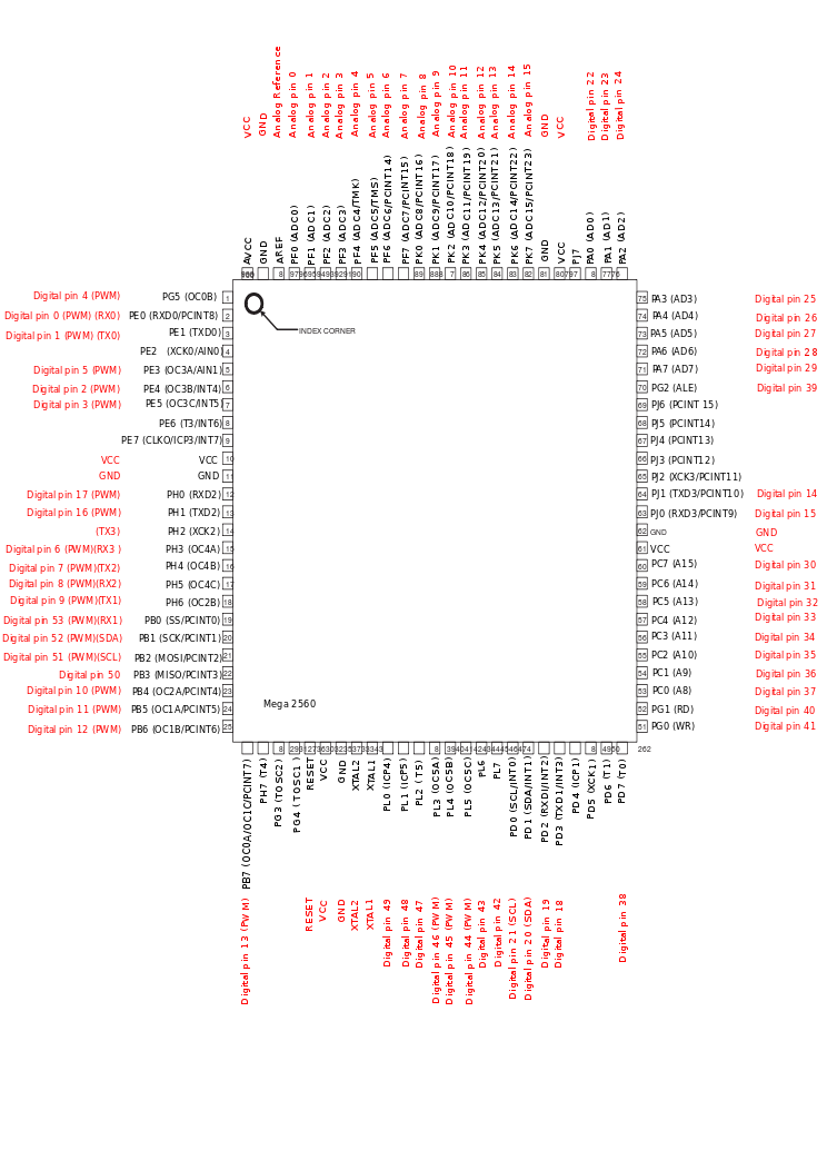
I am neither familiar with the Flydumega board nor the Arduino "Mega", but judging from the pictures, there are plenty of digital output pins available, just pick any of them (e.g. D30). I don't understand why Arduino uses a completely useless naming scheme for the pins, but refer to the pinmapping at http://arduino.cc/en/Hacking/PinMapping2560 to see what register and pin is really behind tat designation:
Digital Pin 30 is actually PC7, so it's the 7th bit of output register C.
Therefore, we can configure and access the pin via DDRC and PORTC:
Using this snippet, your LED should flash once connected to PC7.
Digital Pin 30 is actually PC7, so it's the 7th bit of output register C.
Therefore, we can configure and access the pin via DDRC and PORTC:
Code: Select all
#define LED_FLASHER_DDR DDRC
#define LED_FLASHER_PORT PORTC
#define LED_FLASHER_BIT PORTC7
#define LED_FLASHER_SEQUENCE       ( (uint8_t) (1<<0 | 1<<2) )
#define LED_FLASHER_SEQUENCE_ARMED ( (uint8_t) (1<<0 | 1<<2) )
#define LED_FLASHER_SEQUENCE_MAX   ( (uint8_t) (1<<0 | 1<<2) )
Using this snippet, your LED should flash once connected to PC7.
Re: Patch: LED Flasher
Thank you all! Even I got it to work now!
Re: Patch: LED Flasher
Ok next question how can I create a kind of strobe sequence, like flash twice real short and the off for a second, flash twice very short.. etc.
Re: Patch: LED Flasher
Look at these defines:
The funny looking stuff to the right is an 8 bit binary number; the lowest (1<<0) and the third-lowest (1<<2) bit are set to 1, the others are 0: 00000101
Multiwii cycles through this Byte every second; so every 1/8 seconds (0,125ms) another bit dictates whether the LED is turned on or not.
In this example, the LEDs are off for the first 5/8 of every second, then two flashes occur. Rinse and repeat.
Here are several examples:
0xFF equals 11111111; so the LEDs are lit continously.
0x00 is the oppisite; the LEDs stay inactive.
10101010 (0xAA) is a fast blinking frequency, 11110000 (0xF0) is much slower.
You can play a little bit with the number, use a calculator to get the actual hex representation of the binary code.
LED_FLASHER_SEQUENCE defines the sequence used when the copter is powered up, LED_FLASHER_SEQUENCE_ARMED is used once the motors are spinning, LED_FLASHER_SEQUENCE_MAX is used once LEDMAX is enabled via AUX switch.
I am using this configuration for my copter:
That way, the LEDs are off by default and only start flashing while the engines are spinning. If I am flying in the dark, I can switch them on permanently using one of my AUX channels.
Code: Select all
    #define LED_FLASHER_SEQUENCE       ( (uint8_t) (1<<0 | 1<<2) )
    #define LED_FLASHER_SEQUENCE_ARMED ( (uint8_t) (1<<0 | 1<<2) )
    #define LED_FLASHER_SEQUENCE_MAX   ( (uint8_t) (1<<0 | 1<<2) )
The funny looking stuff to the right is an 8 bit binary number; the lowest (1<<0) and the third-lowest (1<<2) bit are set to 1, the others are 0: 00000101
Multiwii cycles through this Byte every second; so every 1/8 seconds (0,125ms) another bit dictates whether the LED is turned on or not.
In this example, the LEDs are off for the first 5/8 of every second, then two flashes occur. Rinse and repeat.
Here are several examples:
0xFF equals 11111111; so the LEDs are lit continously.
0x00 is the oppisite; the LEDs stay inactive.
10101010 (0xAA) is a fast blinking frequency, 11110000 (0xF0) is much slower.
You can play a little bit with the number, use a calculator to get the actual hex representation of the binary code.
LED_FLASHER_SEQUENCE defines the sequence used when the copter is powered up, LED_FLASHER_SEQUENCE_ARMED is used once the motors are spinning, LED_FLASHER_SEQUENCE_MAX is used once LEDMAX is enabled via AUX switch.
I am using this configuration for my copter:
Code: Select all
    #define LED_FLASHER_SEQUENCE       0x00
    #define LED_FLASHER_SEQUENCE_ARMED ( (uint8_t) (1<<0 | 1<<2) )
    #define LED_FLASHER_SEQUENCE_MAX   0xFF
That way, the LEDs are off by default and only start flashing while the engines are spinning. If I am flying in the dark, I can switch them on permanently using one of my AUX channels.
Re: Patch: LED Flasher
Tommie wrote:I created a little patch to add an effective LED strobe to my copter.
The LEDs are connected to PB4 (using a transistor as a switch), which is toggled by the software during the control loop.
The flash sequence can be modified by setting the define LED_FLASHER_SEQUENCE or even at runtime by calling
led_flasher_set_sequence(uint8_t s): The bits supplied byte specify whether the LED should be turned on (1) or off (0) for
1/8 of a second, so the default setting of 10100000 (LSB to MSB) yields familiar double flashes, 11110000 (0xF0) generates
a slow blinking etc.
I'd love to see this little patch incorporated into the Multiwii code base.
I tried to attach the patch file, but neither .diff nor .patch files are accepted by the board software. How can I contribute?
Hi,
One think, what is the PB4 output on Mega328P?
I have this board http://www.drotek.fr/shop/en/72-multiwi ... c5883.html
Re: Patch: LED Flasher
Neo360 wrote:Hi,
One think, what is the PB4 output on Mega328P?
I have this board http://www.drotek.fr/shop/en/72-multiwi ... c5883.html
Well, PB4 IS the pin identifier for the ATMega. It maps to digital pin 12 on an Atmega238p-based Arduino Duemilanove or Uno if that's what you mean.
http://arduino.cc/hu/Hacking/PinMapping
Re: Patch: LED Flasher
fiendie wrote:Neo360 wrote:Hi,
One think, what is the PB4 output on Mega328P?
I have this board http://www.drotek.fr/shop/en/72-multiwi ... c5883.html
Well, PB4 IS the pin identifier for the ATMega. It maps to digital pin 12 on an Atmega238p-based Arduino Duemilanove or Uno if that's what you mean.
http://arduino.cc/hu/Hacking/PinMapping
Ok i find the pb4 out.
Another think
Re: Patch: LED Flasher
Neo360 wrote:Another think
If you want to switch against GND you need an NPN transistor:
Code: Select all
 +12V o-------------------------+
                               |
                              .-.
                             ( X )
                              '-'
                               |
                    ___      |/ T1,NPN
        uC PIN o---|___|-----| BC547
                   R2,4K7    |>
                               |
GND o---------o--------------+Re: Patch: LED Flasher
I try with my PNP transistor but dont flash always on.
Wiring:
Emiter to +BATT, Base via 2,2k resistor to port B4, Collector to LED+ and LED- to ground.
Wiring:
Emiter to +BATT, Base via 2,2k resistor to port B4, Collector to LED+ and LED- to ground.
Re: Patch: LED Flasher
what LED light do you use for the flasher?
thanks
thanks
-
kataventos
- Posts: 702
- Joined: Sun Aug 28, 2011 8:14 pm
- Contact:
Re: Patch: LED Flasher
Thank you Tommie
Re: Patch: LED Flasher
Hi !
thanks for the LED Flasher in the MW code
so far i just tried to "route it" to the internal LED, which is in my case a "paris board" and the LED is on a13/ PB5.
also i have 2 spare channels .. eg. PB4.
i changed the code to:
but still compiling is not possible:
huh? what did i miss here?
or is it simply not possible to have, "just for testing purpose" the onboard LED used for the "led flasher" routine?!
therefore i though i use my 2 unused channels.. which are meant to trigger the camtrigger (but disabled by code).
sorry for my accent, i am german
thank you very much
regArts
Dennis
thanks for the LED Flasher in the MW code
so far i just tried to "route it" to the internal LED, which is in my case a "paris board" and the LED is on a13/ PB5.
also i have 2 spare channels .. eg. PB4.
i changed the code to:
Code: Select all
   #define LED_FLASHER
    #define LED_FLASHER_DDR DDRB
    #define LED_FLASHER_PORT PORTB
    #define LED_FLASHER_BIT PORTB5
    #define LED_FLASHER_SEQUENCE ( (uint8_t) 0 )
    // create double flashes
    #define LED_FLASHER_SEQUENCE_ARMED ( (uint8_t) (1<<0 | 1<<2) )
    // full illumination
    #define LED_FLASHER_SEQUENCE_MAX 0xFF
but still compiling is not possible:
quadx21_cam_GPS_sum_LEDCONF.ino: In function 'void blinkLED(uint8_t, uint8_t, uint8_t)':
quadx21_cam_GPS_sum_LEDCONF:296: error: 'switch_led_flasher' was not declared in this scope
quadx21_cam_GPS_sum_LEDCONF.ino: In function 'void annexCode()':
quadx21_cam_GPS_sum_LEDCONF:431: error: 'auto_switch_led_flasher' was not declared in this scope
quadx21_cam_GPS_sum_LEDCONF.ino: In function 'void setup()':
quadx21_cam_GPS_sum_LEDCONF:572: error: 'init_led_flasher' was not declared in this scope
quadx21_cam_GPS_sum_LEDCONF:573: error: 'led_flasher_set_sequence' was not declared in this scope
quadx21_cam_GPS_sum_LEDCONF.ino: In function 'void loop()':
quadx21_cam_GPS_sum_LEDCONF:756: error: 'led_flasher_autoselect_sequence' was not declared in this scope
huh? what did i miss here?
or is it simply not possible to have, "just for testing purpose" the onboard LED used for the "led flasher" routine?!
therefore i though i use my 2 unused channels.. which are meant to trigger the camtrigger (but disabled by code).
sorry for my accent, i am german
thank you very much
regArts
Dennis
Re: Patch: LED Flasher
What has changed with this feature now that 2.2 has been released. I noticed we now have a LOW and INVERT setting. How do these work.
Also, now that there is no AUX switch for LEDMAX, how can we toggle this?
Also, now that there is no AUX switch for LEDMAX, how can we toggle this?
Re: Patch: LED Flasher
You can toggle this in the GUI. (Only when the Flasher is active in the Sketch!)
Last edited by Stars112 on Fri Mar 29, 2013 10:01 pm, edited 1 time in total.
Re: Patch: LED Flasher
Stars112 wrote:You can toggle this in the GUI. (Only when the Flasher is active in the Skatch!)
ohh good to know. I wasnt aware that the gui options now disappear when not turned on in sketch.
-
jevermeister

- Posts: 708
- Joined: Wed Jul 20, 2011 8:56 am
- Contact:
Re: Patch: LED Flasher
Hi,
I just isntalled a transistor today - really nice work Tommie.
Blinking LEDs gave my copter the extra look.
Nils
I just isntalled a transistor today - really nice work Tommie.
Blinking LEDs gave my copter the extra look.
Nils