FAQ
Contents
- 1 Acronyms
- 2 General
- 2.1 LED status signification
- 2.2 Choosing another ESC/motor/propeller
- 2.3 Arduino seems to operate well (LED is blinking shortly at the initialization), but it’s impossible to connect the GUI
- 2.4 I’m not a programmer nor an electronics. Is it difficult to build and setup ?
- 2.5 Is a multicopter difficult to fly ?
- 2.6 The stable mode is not so stable
- 2.7 You have a question you think is not yet discussed here
- 3 Starting, running & stopping MultiWii
- 3.1 The motors do not start
- 3.2 The motors still do not start or start but do not stop any more
- 3.3 The motors still do not start, what about the minimum throttle signal send to the ESC’s
- 3.4 The motors start & stop but after trimming the yaw it’s no longer possible to start or stop the motors
- 3.5 Be sure your ESC can support PPM with 490Hz refresh rate
- 3.6 Why is it important to define the minimum running value for the ESCs ?
- 3.7 One motor stops suddenly in a flight
- 3.8 How to trim your Copter
- 4 Wii Motion Plus related
- 5 Servos
- 6 Connecting elements
- 7 Graphical User Interface
- 7.1 The values in the GUI do not seem to work or update
- 7.2 The ACC values are stuck to +/-400
- 7.3 The GUI seems to lock up or freezes during connection.
- 7.4 The GUI itself doesn’t start or seems to give some errors
- 7.5 The motor output on the GUI is not equal on both sides with a neutral RC input
- 7.6 How should be the sensor axis directions
- 8 Arduino
- 9 Interesting links
Acronyms
ACC: Accelerometer (this could be either the Nunchuck or other individual sensors)
CG or COG: Centre of gravity
NK: Nunchuk
I2C: Inter IC, It’s actually the communication bus which is used by all the MultiWiiCopter sensors. (More detailed info here or here.)
SCL: I2C communication bus wire.SCL is the clock line. It is used to synchronize all data transfers over the I2C bus.
SDA: I2C communication bus wire. SDA is the data line
WMP or WM+ or MP: Wii Motion Plus
General
LED status signification
a short blink means there is no ACC connected (Nunchuk or other)
a long blink means there is an ACC connected (Nunchuk well recognized or other)
[[During field setup via LCD: ]]
there is a fast blink at the beginning of the setup mode, and at the end
there is a fast blink when a parameter is increased/decreased, and when the parameter is changed
LED is ON when the motors are armed
LED is OFF when the motors are not armed
The blinks at the initialization is very long (more than 5s): it is sometimes the case with a WMP+NK configuration. A way to correct this is to increase the INTERLEAVING DELAY in the sketch. (from 3000 to 3500 or 4000)
The LED is permanently blinking: it indicates a wrong connection between I2C devices and the Arduino (maybe a switch between SCA and SCL lines)
After trying to arm, the LED stays off: check your RX connection and set correctly the radio end point to match the range 1000-2000 in the GUI
Choosing another ESC/motor/propeller
The propeller should be are light as it can be. GWS SF is a good choice in every dimension.
For a given consumption, the proportion pitch/diameter should be the lowest (10×3.8 is better than 10×4.7. And 10×4.7 is better than 8×6)
Motors KV should be low. It’s better for the efficiency and for the spinning resolution.
You can find on warthox blog several proven to work configs: http://warthox.bplaced.net/?page_id=76
Arduino seems to operate well (LED is blinking shortly at the initialization), but it’s impossible to connect the GUI
If you are using windows, the port COM needs something to be reconfigured to run at 115200Hz.
I’m not a programmer nor an electronics. Is it difficult to build and setup ?
The minimal knowledge is to be able to understand the Arduino world, and being able to load the “Hello world” or LED blink sketch.
I thing it’s possible in few hours, and this step is essential.
If you don’t know what is a sketch or if you don’t know how to communicate with an Arduino board, you can’t go further.
Hopefully, the getting start topics on Arduino are very well done.
Arduino is very documented, especially for people who are not specialists at all.
You can first read this page to begin in this environment and learn how to upload a code in a board. http://arduino.cc/en/Guide/Windows
Is a multicopter difficult to fly ?
I don’t recommend it for your first RC experience. I advice every very beginner to start with a coaxial helicopter like the LAMA.
A multicopter is generally very stable, but it doesn’t stay itself in the air ;)
The stable mode is not so stable
In the stable mode, multiwii try to level horizontally the copter when the sitcks are released.
It doesn’t mean the copter will not move.
Nothing prevent the copter from sliding in this mode, so don’t expect too much about it.
You have a question you think is not yet discussed here
Ask it in the Getting Started section of the forum.
Starting, running & stopping MultiWii
The motors do not start
Move the rudder full right with throttle all the way down to start the motors, full left to turn off the motors.
If the LED stays off, it is a problem related to the RX setup.
If the LED is going ON after the arming procedure, it is a problem related to the ESCs.
The motors still do not start or start but do not stop any more
You have to adjust the travel of your channels so it has a range from 1000 to 2000 on the GUI.
Most likely you need to extend your channel endpoints on your transmitter so the minimum & maximum request is changing from 1000 to 2000.
For Graupner/JR radio, it implies an ATV of 125% for all channels.
On most radios, the endpoints or travel adjusts must be increased to approximately 120% till140%. to get a 1000 to 2000 range in the GUI.
If this range is not matched, the arming level value can’t be reached on the yaw channel, and it’s not possible to arm the motors.
Before trying to operate the MultiWii copter, it’s important to set the end points with the help of the GUI.
The motors still do not start, what about the minimum throttle signal send to the ESC’s
In some cases the ESC’s do not start with the supplied standard minimum throttle value.
It’s possible to lower this value in order to start the ESC’s.
One can try to lower the MINCOMMAND value with steps of 50 to 950 or 900.
The motors start & stop but after trimming the yaw it’s no longer possible to start or stop the motors
By setting the trim, the complete range moves up or down so the endpoint does not reach the desired 1000 or 2000 any more.
One transmitter suffering from this is e.g. the very basic Planet T5 2.4Ghz transmitter.
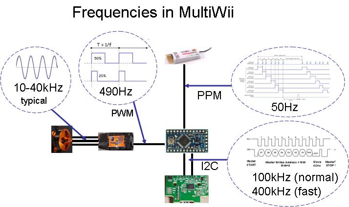
Be sure your ESC can support PPM with 490Hz refresh rate
For the MultiWii we need a fast update rate & ESC’s which can handle that.
There are a number of standard ESCs than can handle update rates of about 490 Hz, namely Turnigy Plush, Mystery Blue, HK SS and a few others.
The 490Hz basically means that the ESC gets 490 times per second an update.
A standard servo for example works at 50hz or is updated 50 times per second.
Here is a diagram with the different frequencies used in the MultiWii project
[img]http://static.rcgroups.net/forums/attachments/2/6/7/7/0/3/a3627948-90-freq.jpg?d=1291043990[/img]
Why is it important to define the minimum running value for the ESCs ?
The motors should always run whatever the situation in flight:
ESCs and motors are not perfect and does not synchronize every time at the beginning. If this happens in the air, one motor won’t be able to spin and I let you imagine the situation.
Gyro-induced corrections can put a ESC in a situation where it is under its running limit (motor stop). It should not be important because it lasts a fraction of second and propellers have some inertia. But I observed a very annoying behavior with Turnigy Plush ESCs: once it is below the running limit, the ESC reaction time to return into the running range is very high, causing crashing oscillations.
If you choose another ESC, you have to tweak this “minimum spinning value”.
The value depends also of the way the ESCs ware calibrated.
Once armed, if the motors are not running, this value must be changed.
This parameter is very important and has to be edited to compile arduino code.
It is one of the key to have a stable multicopter in descent.
One motor stops suddenly in a flight
It may occur if your ESC is configured in soft mode.
It is preferable to set the ESCs in MEDIUM or HIGH mode.
A simple test to check this problem:
- hold the multicopter firmly in your hand
- start the motors and put a little throttle (enough to feel the gyro correction)
- shake it to counter the motor reaction
- if one motor stops, the problem is then related to motor-ESC combination and you probably need to adjust the timing
How to trim your Copter
1. Trim in “acro”:
Calibration is made on each power on, but you can do it manually like before:
Full throttle down + full yaw left + full pitch backward
Just fly in acro mode and trim your copter with the trims on your transmitter.
No need to land, just do it in the air and trim as long as it looks good for you.
2. Trim in “stable” = ACC mode:
1. You have to trim your copter in “acro” mode before.
So your copter is perfectly trimmed in acro mode.
Otherwise you are overmixing trims from acro mode to stable mode and you have to trim stable mode again.
2. You have to calibrate ACC.
Copter must be stable and level at the ground.
Motors disarmed.
Full throttle up + full yaw left + full pitch backward
3. Now start motors and fly in stable mode.
Normally its better to start here as normal in acro mode and switch to stable mode while in the air.
Because if stable mode needs much trim, its easier to fly in acro mode.
Okay, so you are now with stable mode in the air and the copter drifts to the right and backwards.
Switch back to acro (easier to land) and land your copter.
Disarm motors.
4. Now trim the ACC mode.
Don’t touch your trims on the transmitter.
Give full throttle (must be >1900)
With the help of your roll and pitch stick you could now trim the ACC mode. full PITCH forward/backward and full ROLL left/right (2 axis possibilities) will trim the level mode according to the neutral angle you want to change.
The status LED will blink to confirm each ticks.
So for instance, you have to move the pitch stick full forward about 4-5x.
That means from neutral to full and back to neutral, 4-5 times.
You will here the buzzer each time beep and see the led each time blink, when move full forward.
The same for the roll axis.
After that start your motors and do again 3. until your copter is complete in level in ACC mode.
If you want to reset the ACC trims, just do step 2. (ACC calibration)
Some times, the gyros seem to be inefficient or erratic
There are a lot of copies of WMP in circulation on ebay. They are working pretty well, however the electronic used to handle gyros differs.
There are several things that can be done to decrease bad inits:
add pull up resistances on the I2C wires. It’s possible to activate the pull up resistances in the atmel 328p, but in some case (long distance, noisy environment) they are not low enough.
decrease the voltage. WMP are normally powered under 3.3V. 5V is ok because there is an internal regulator, but at 3.3V, it seems to work better.
WMP uses fast I2C mode at 400kHz. In some cases, especially for original WMP, this increase the rate of bad inits. A corrective way is to leave I2C rate in normal mode: comment/uncomment the line in the sketch dealing with I2C speed.
Hopefully, in many cases, there is no problem at all regarding the WMP initialization.
400kHz or 100kHz I2C speed?
An original motion plus generally runs only at 100kHz, some clones work perfectly on 400kHz but this is not the case for all clone versions.
Some experience more WM+ freezes when the WM+ is running at 400kHz.
It’s certainly no problem to run at 100kHz most people will not notice any difference.
In general it’s better to start with the I2C communication at 100Khz excluding possible errors.
Note, this has nothing to do with the ESC update rate.
Cycle time
With a WMP only configuration, the cycle time should be something like 2000 at 400kHz, and 3300 at 100kHz.
With a WMP+NK configuration: the cycle time should be always around 6000 whatever the I2C speed.
If the cycle time is different, you must increase INTERLEAVING DELAY.
The cycle time is good when it is 2x INTERLEAVING DELAY.
Generally speaking, the cycle should be maintained low to have a reactive and stable multi.
However, the difference is not always noticable for quite static flights.
Servos
Is it possible to have a camera TILT compensation with 2 servos ?
With an arduino based on Atmel 328p (Pro Mini or Uno):
configuration with 4 motor or less: 2 servos (pitch AND roll) can be used optionally
configuration with 6 motors: no servo
With an arduino based on Atmel 1280 (Mega or Flyduino):
it’s possible with all configuration
Is it possible to command a camera inclination with the TX while flying ?
Yes it is possible since v1.8
You need to have access to the 7th and 8th channel (named CAM PITCH and CAM ROLL)
So, for a promini, it means a PPM SUM receiver. And for MEGA boards, any receiver.
The PITCH/ROLL RC superposition is activated in the GUI via the CAMSTAB option. (You still need to activate the #define SERVO_TILT option before in config.h)
Connecting elements
What about the diodes, 3.3V voltage regulators & pin 12?
With a WMP
The WM+ has an on board voltage regulator and works perfectly with a 5VDC supply.
It is powered directly with via D12 to be able to reset it quickly in case of failure.
A NK can be connected optionality on the WM+.
Alternatively, the WM+ can be powered from 5VDC or from 3.3VDC continuously, but note that the software cannot reset in this case the WM+ if the I2C communication bus freezes.
The reset option has saved already several quads & tricopters from hard crashes!
Optional I2C sensors works only if powered with 3.3VDC.
The voltage reduction from 5V to 3.3V can be done by placing 2 diodes in series with the sensors or by connecting an 3.3V voltage regulator (LM1117).
Of course other options are possible. E.g. powering it from the 3.3V from an Arduino board with 3.3V available.
There is no need to reset other I2C sensors, because they never freeze the lines.
Without a WMP
All sensors must be powered with 3.3V, via a voltage regulator, or via placing 2 diodes in series to reduce the voltage.
How & where should the be mounted the sensors on the board/model
The gyro position is not so important, but the ACC position should be as close as possible to the CG.
The gyro and ACC orientation is very important.
This orientation is explained one the main schemes, just follow the blue arrow.
Is a PPM converter necessary ?
The PPM sum signal is only mandatory for the Y6 or Hexa one a Arduino 328p based hardware.
The reason is tied to I/O PIN number limitation and this hardware.
For other setup (MEGA or less motors), it is optional.
Some receivers have a direct ppm output stream, they can be used because it would represent less wiring and the remaining input pins on the Arduino are then not used.
ESC setting
Basically:
the ESCs should be configured in NI-MH to prevent a cutting off motor due to low battery.
the ESCs should be set on middle to high timing to avoid a motor stop failure while flying
Graphical User Interface
The values in the GUI do not seem to work or update
The ACC & gyro values are only displayed in the GUI if everything is connected & running
It’s however possible to see some data without the RC connected.
The ACC values are stuck to +/-400
This is one of the most common issue with ACC.
The accelerometers need to be calibrated at least once via the RC sticks combination (low throttle + pitch stick low + yaw full left).
Once this step is done, the accelerometer neutral value is stored in the EEPROM.
Without this step, the accelerometer values won’t correspond to anything, and sometimes there are anarchical bars in the GUI.
The values are typically 0/0/200 or 0/0/250 or 0/0/512 after a good calibration, depending on the ACC type.
The GUI seems to lock up or freezes during connection.
Make sure you are not going to fast, in general it seems better to wait a few seconds between & before the start command on the GUI is given.
General advise:
Boot arduino
Start Configurator
wait a few seconds
click “start”
wait
if WMP data, click read
wait… move quad a little
ACC data shows up…
If it fails (locks up), exit the configurator and try again.
Also, on the mac, if I do not choose the correct serial port (USBSERIAL) or did not install the drivers, it locks up when you select the serial port.
It does work though, it just takes a few tries to make the connection.
The GUI itself doesn’t start or seems to give some errors
Make sure you have the correct JAVA runtime installed, the latest version can be downloaded here.
If you encounter problems with JAVA, I recommend uninstalling your current JAVA version and installing the latest version again.
If possible, try to run the software from another computer.
The GUI version is generally only compatible with the sketch version (MultiWii sketch 1.5 vs MutiWiiConf 1.5 for instance)
The motor output on the GUI is not equal on both sides with a neutral RC input
This is the normal PID loop behaviour, the I-term is actually cumulating the error over time & tries to compensate for that but the copter is hand-held or fixed on the table.
When the I-term is zeroed, the this will not happen.
A flying multicopter will actually use the I-term in the PID to correct itself again to the same level as before the disturbance.
How should be the sensor axis directions
TILT the MULTI to the RIGHT (left side up):
MAG_ROLL, ACC_ROLL and GYRO_ROLL goes up
MAG_Z and ACC_Z goes down
TILT the MULTI forward (tail up):
MAG_PITCH, ACC_PITCH and GYRO_PITCH goes up
MAG_Z and ACC_Z goes down
Rotating the copter clockwise (YAW):
GYRO_YAW goes up
MAG_Z is positive
ACC_Z is positive
Arduino
sketch too large error
The software is written for an ATmega328 or an ATMega 1280 depending on your board.
This problem may happen when a wrong (smaller) board is selected.
MINTHROTTLE was not declared in this scope
In the configurable parameters you need to uncomment (and maybe find the good value) the line relative to MINTHROTTLE
//#define MINTHROTTLE 1300 // for Turnigy Plush ESCs 10A //#define MINTHROTTLE 1120 // for Super Simple ESCs 10A
Interesting links
kinderkram blog
The excellent blog of kinderkram is here:
http://www.rcgroups.com/forums/showthread.php?t=1332876
It’s a “step by step” construction approach
Berkely documentation
http://www.rcgroups.com/forums/showthread.php?t=1340771#post16587954
connection diagrams, FAQs, list of existing adapter boards
The current FAQ (on multiwii.com) is mainly based on Berkely’s FAQ.
There are some more details in it, with links to the rc-groups post where each problems were discussed.
A must read
Shikra guide
I recommend strongly every beginner to read Shikra step by step setup progression:
http://www.rcgroups.com/forums/showthread.php?t=1348268
tricopter oriented
PID tuning theory and configuration guide
http://www.rcgroups.com/forums/showthread.php?t=1375728
The “huge post” on rcgroups forum
http://www.rcgroups.com/forums/showthread.php?t=1261382
maybe too huge ;)
UndCon’s MultiWii configurations via stick input
http://www.undcon.com/2010/09/24/mul…onfigurations/
Spag’s database and survey on WMC settings and PID tuning
survey: https://spreadsheets.google.com/viewform?formkey=dE1EWHRTenVieFRxb09iMFVqTUtKQlE6MQ
response: https://spreadsheets.google.com/viewanalytics?formkey=dE1EWHRTenVieFRxb09iMFVqTUtKQlE6MQ
will move this stuff to the trouble shooting page and then use it for general MWC faq'
Vibrations
The sensors are very sensitive to the vibration and they can’t give the right data reading to the MCU if there are noises and vibrations. Here you can see an example video of the sensors telemetry of a flying quadcopter with low noise in the readings.
balancing all brushless motors
The motor case are always not perfectly balanced, so you might get one side who has more weight than the other side. When it runs at high speed it makes some vibration.
To balance a brushless motor with some tape you need to do only 2 things.
- you have to know where you put the tape to add some weight
- you have to know how much tape/weight you have to add.
You don’t need any special tool to make this done.
- Turn on your motor to balance and look the data read in the GUI
- remember how bad the curves you get.
- put anywhere a piece of tape on the motor case and turn on your motor again.
- You’ll see the curves are better if you are on the right side
- worse if you are on the wrong side.
- If you are on the wrong side go to have a try on the other side.
- If you have better data read you should move the tape a little bit to right or to left and see if the data reading becomes better than better.
- if better than better just continue to move the tape further until the data reading becomes worse and than move back a little bit.
propeller balancing
To limit maximum vibration after balancing the motors you’d better to balance the propellers. Plastique propeller is made from molds. The quality depends firstly on the machining of the molds and secondly the molding skills.