Excalibur, I reply to you in the public thread, so it will be usefull for others:
Here you are how it's defined in def.h file:
Code: Select all
#if defined(SONAR_GENERIC_ECHOPULSE)
  #define SONAR_GEP_TriggerPin             12
  #define SONAR_GEP_TriggerPin_PINMODE_OUT pinMode(SONAR_GEP_TriggerPin,OUTPUT);
  #define SONAR_GEP_TriggerPin_PIN_HIGH    PORTB |= 1<<6;
  #define SONAR_GEP_TriggerPin_PIN_LOW     PORTB &= ~(1<<6);
  #define SONAR_GEP_EchoPin                11
  #define SONAR_GEP_EchoPin_PINMODE_IN     pinMode(SONAR_GEP_EchoPin,INPUT);
  #define SONAR_GEP_EchoPin_PCINT          PCINT5
  #define SONAR_GEP_EchoPin_PCICR          PCICR |= (1<<PCIE0); // PCINT 0-7 belong to PCIE0
  #define SONAR_GEP_EchoPin_PCMSK          PCMSK0 = (1<<SONAR_GEP_EchoPin_PCINT); // Mask Pin PCINT5 - all other PIns PCINT0-7 are not allowed to create interrupts!
  #define SONAR_GEP_EchoPin_PCINT_vect     PCINT0_vect  // PCINT0-7 belog PCINT0_vect
  #define SONAR_GEP_EchoPin_PIN            PINB  // PCINT0-7 belong to PINB
#endif
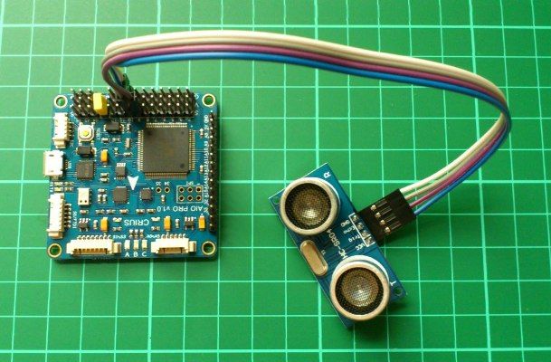
So, yo only need to connect Triger to signal pin 12, and Echo to signal pin 11, exactly the pins with same numbers as you see on the board. Also you need to connect vcc and gnd wires to the vcc pin and gnd pin 12 or 11, any of them is the same.
The image linked inside the thread of the forum is not correct, it use other pins. If you use the code above as it is defined, you must use pins 11 and 12 of your board. Thats all.
Don't forget to define generic sonar in config.h:
Code: Select all
/* Generic sonar: hc-sr04, srf04, dyp-me007, all generic sonar with echo/pulse pin
         default pulse is PH6/12, echo is PB4/11
      */
      #define SONAR_GENERIC_ECHOPULSE
      #define SONAR_GENERIC_SCALE 58 //scale for ranging conversion (hcsr04 is 58)
      //#define SONAR_GENERIC_MAX_RANGE 500 //cm (could be more)
      #define SONAR_GENERIC_MAX_RANGE 450
I use 450 cm as max range because this is the value in the specs from the supplier where i bought it.
Sorry for not sending an image of my quad, but I have to disassemble many parts to do a good photo, but if you do what I say it will work nice.