brm wrote:the overshoot you noticed causes the noise to be amplified.
Very strange conclusion, I would say
The overshoot and ringing effect can be visualized during acc calibration process. When one places FC in level and hits CALIB_ACC button, ACC Z readings suddenly (during one sample) changes from 1G to 0 and stays at 0 for quite a long time. This is a step function and one can see overshoot + ringing on the ACC_Z graph. This is the price we have to pay for really good frequency separation and fast execution time. In the real world under normal conditions it is almost impossible to produce a step function. Therefore overshoot and ringing effect is negligible in filtering process of the real sensors data.
Yesterday I did some modeling and found out that previously proposed 6-th order Chebyshev filter using precision of the float variables rings/oscillates. Oscillations are not observed when using filters of the 4-th order.
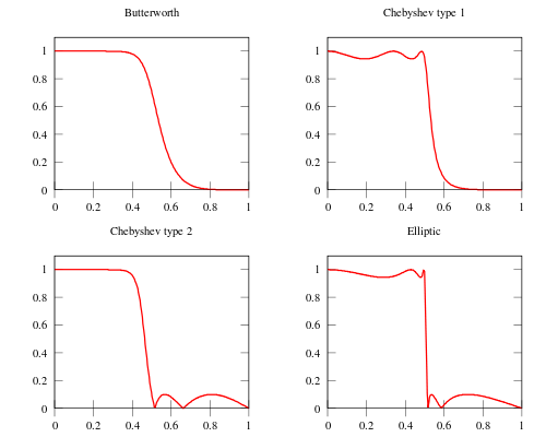
To correct the oscillation problem and minimize overshoot in step function responce I calculated coefficients for Butterworth filter. This is the 4-th order IIR filter with 5Hz cut-off (looptime=5000) frequency (more then enough for complimentary filter with gyro_cmpf_factor = 400). Filter doesn’t oscillate using float precission and is implemented as a feature.
To enable Butterworth filter using CLI interface, one has to type “feature IIR_LPF” and acc_lpf_factor has to be greater than 0 (e.g. “set acc_lpf_factor = 10”).