CJMCU microquad board

Romushock
Posts: 11
Joined: Fri May 30, 2014 3:55 pm

CJMCU microquad board

Post by Romushock »

Hi to everyone. I hope to find here STM32 experts who want to ask for advice. Some days ago I receive this board.
DSCF9659.jpg
DSCF9667.jpg
DSCF9660.jpg

By the labeling, I can not understand how to connect the receiver. The seller have no information. The board has a lot of pads, but they are labeled as STM32 pinouts.
DSCF9662.jpg
DSCF9663.jpg
DSCF9664.jpg
DSCF9668.jpg

It is clear that 3V3, GND, TX1 and RX1 - are for FTDI. And what the others? Is it possible to connect here baro by I2C?
For some years I have other microquad board from CJMCU, but this one based on M328 and I haven't any problems to make it fly.
DSCF9670.jpg

So, any input is highly appreciated ;) Thank all in advance for the tips.

timecop
Posts: 1880
Joined: Fri Sep 02, 2011 4:48 pm

Re: CJMCU microquad board

Post by timecop »

Does this help?
http://www.abusemark.com/downloads/mb337_pinout.png
you could probably attach PPM receiver to PA0. No idea what brushed motors are connected to.
Baseflight will probably not run as-is - might need some changes to outputs.

Romushock
Posts: 11
Joined: Fri May 30, 2014 3:55 pm

Re: CJMCU microquad board

Post by Romushock »

Thanks, TC, I'll try :D

mj666
Posts: 186
Joined: Wed Feb 12, 2014 12:02 pm

Re: CJMCU microquad board

Post by mj666 »

Also bought two of them now and they arrived last days. The controller comes without any firmware and the vendor does not provide any additional information. At the moment Baseflight is supporting brushed motors out of the box. I already flashed latest Baseflight successfully but it does not start. Unlike earlier STM32F103C8T6 the ones used here really look to have only 64kb of flash memory as advertised in the related product sheet. This is what the flashtool is seeing but I will do some more testing to finally verify. Baseflight still fits in 64kb but most likely expects the emulated eeprom area in the last block of the 128kb flash. I guess this is the problem why the code does not work. Baseflight is only below 64kb if compiled with the commercial Keil ARM MDK toolchain. With the GNU toolchain it get bigger then this. Actual I see 3 options to proceed:

1. Find someone with the Keil ARM MDK toolchain to help to compile a variant for this Quad.
2. Remove some unneeded functionality (GPS, SONAR, etc.) to reduce the final code size of Baseflight to be able to compile with GNU tooolchain and end up below 64kb.
3. Replace the STM32F103C8T6 with a STM32F103CBT6 chip (hot air station is available). This will not be an option for regular users and is the worst case scenario.

I also will trace the motor signals and led connection to verify if the layout is compliant with Baseflight or additional adjustments are needed. I'm planning to use a Deltang RX31 in PPM mode as the receiver. Does someone has a good idea how to fix the motors. I don't like the idea to solder them in. I will try to use shrink tube to get them fixed but not sure yet if this will work. Any feedback is welcome.

Before proceeding with this I'm also working to get a similar build with and ATMega 238 with regular MultiWii working but I'm already quite far with this project and expect to have this finished in 1-2 days.

http://www.goodluckbuy.com/cjmcu-v3-mwc-micro-flight-control-10dof-120mm-wheelbase-mini-quadcopter.html

I will keep you posted about my progress.

timecop
Posts: 1880
Joined: Fri Sep 02, 2011 4:48 pm

Re: CJMCU microquad board

Post by timecop »

Do you know if motor pinout matches that of baseflight?
I can check flash size register and adjust flash location accordingly, if that would make firmware run on them.
But yes, we're getting very close to 64k even with armcc - 60.1k currently.
There's a fair bit of cruft in the code that can go tho, and bunch of size-inflating shit in telemetry and couple other places, I wish I had time to go through it and trash some of the stuff, but I dont :(

mj666
Posts: 186
Joined: Wed Feb 12, 2014 12:02 pm

Re: CJMCU microquad board

Post by mj666 »

Would be worth a try to make a hex with the following change in conf.c:

#define FLASH_WRITE_ADDR (0x08000000 + (uint32_t)FLASH_PAGE_SIZE * (FLASH_PAGE_COUNT - 2)) // use the last 2 KB for storage
to
#define FLASH_WRITE_ADDR (0x04000000 + (uint32_t)FLASH_PAGE_SIZE * (FLASH_PAGE_COUNT - 2)) // use the last 2 KB for storage

I can upload and see if it will start up properly (LED's are working, CLI is responding, GUI will receive information's). Still need to trace Motor pins to see if they fit the Baseflight setup. There is not much else on the board which will make it complicated STM, MPU and MÁG. Could not find a voltage divider for power monitoring or anything else special. There are mainly capacitors not many resistors and the are mainly used for the LED's and the brushed motor controllers. Not sure if someone has this really working. Could not find much information at the web. But the idea of a BCP Microquad with Baseflight and the price makes me interested. Its a cool project. The remaining space is very tide but for now it should work. For later it's may be possible to cut down functionality, anyhow for Acro flying Baseflight is more than perfect and additional functionality is not needed for this micro. So stick with an actual firmware level is may be also not a problem if we get this working.

timecop
Posts: 1880
Joined: Fri Sep 02, 2011 4:48 pm

Re: CJMCU microquad board

Post by timecop »

I just did it properly, download latest hex and try it.

mj666
Posts: 186
Joined: Wed Feb 12, 2014 12:02 pm

Re: CJMCU microquad board

Post by mj666 »

Hello timecop thanks very much for the fast response and the immediate action. Just downloaded and will give it a try this evening when back home.

mj666
Posts: 186
Joined: Wed Feb 12, 2014 12:02 pm

Re: CJMCU microquad board

Post by mj666 »

Just tested the new hex. The behavior has not changed. In the meantime I trace some pins:

Led1: Pin2 PC13
Led2: Pin3 PC14
Led3: Pin4 PC15
Motor1 Pin45 PB8 TIM4_CH3
Motor2 Pin46 PB9 TIM4_CH4
Motor3 Pin18 PB0 TIM3_CH3
Motor4 Pin19 PB1 TIM3_CH4
TX1 Pin30 PA9 USART1_TX
RX1 Pin31 PA10 USART1_RX
SCL Pin42 PB6 I2C1_SCL using external pullup
SDA Pin43 PB7 I2C1_SDA using external pullup

This is not compliant with the NAZE32.
Last edited by mj666 on Fri Jun 27, 2014 3:44 pm, edited 1 time in total.

timecop
Posts: 1880
Joined: Fri Sep 02, 2011 4:48 pm

Re: CJMCU microquad board

Post by timecop »

ugh, they're using I2C peripheral on a remap?
That's going to be annoyingly hard to support without building different firmware :(

mj666
Posts: 186
Joined: Wed Feb 12, 2014 12:02 pm

Re: CJMCU microquad board

Post by mj666 »

In my understanding the I2C pins are only an alternative I2C port of the STM32 and there is no function remap required. If we make a similar setup like the OLIMEXINO we can remap the pins and also reduce the size since we can remove functionally not needed (will help to use the free toolchain with the limited flash). The only challenge would be the change of the i2C port but this changes looks to be concentrated to the drv_i2c.c. The i2c port pins are hardcoded there. I would make a try on this but unfortunately I was never able to build the OLIMEXINO target with the GNU toolchain. Calling make NAZE or make OLIMEXINO never worked. I only can do make and it will build NAZE as default. May be modify the default in the makefile will make it work. There was no real reason for getting this to work in the past. I also have not traced the MAG pins yet if it is directly at the I2C port or connected to the MPU.

timecop
Posts: 1880
Joined: Fri Sep 02, 2011 4:48 pm

Re: CJMCU microquad board

Post by timecop »

You are right, its not a remap, just different peripheral (1 vs 2)
I2C device isn't hardcoded (I think there's a I2Cx pointer at the top of the file for the peripheral),
but I see that dummy clockout stuff is - I should probably fix that.

Other than that, its just the PWM and led mapping.
Can't be done at runtime tho - would need rebuild.

mj666
Posts: 186
Joined: Wed Feb 12, 2014 12:02 pm

Re: CJMCU microquad board

Post by mj666 »

The flash locks be larger since I can load a self compiled HEX with 77 blocks without errors? I started to remap the pins (LED’s, motors pins and I2C). I used LED2 and LED3 since the port for LED1 interferes with an baro pin. Reorderd the PWM channels in drv_timer.c. Move the 4 motor channels in the first 4 motor PWM slots and replace two timers used by I2c port with the 2 which get available from the I2C swap. Directly after flashing the LED’s start to blink each abbot 2 seconds. But if I power off and on again the blinking will not come back and I have no reaction at the LED’s and also no CLI response. Will keep trying.

timecop
Posts: 1880
Joined: Fri Sep 02, 2011 4:48 pm

Re: CJMCU microquad board

Post by timecop »

I just pushed code that makes I2C setup generic. All you need to do is change i2cInit() in drv_system to use I2CDEV_1.
So there is less code for you to edit. Maybe at some point we can do platform define to fix PWM maps and leds etc.

mj666
Posts: 186
Joined: Wed Feb 12, 2014 12:02 pm

Re: CJMCU microquad board

Post by mj666 »

Timecop thanks for moving forward this fast and help to drive this project. I have downloaded the new code and done my changes. Unfortunately it does not make a positive difference so there must be something else which does not fit. Now only LED1 is going on immediately after flashing. No other reactions. After repowering no reaction at all as before. I compiled your original code and tested it at one of my AfroMini 32 and it works as expected (noting is connected yet but LEF’s and CLI, GUI is working). So I don’t have a problem with my compile process. Anyhow this was always working in the past to build Baseflight and Harakiri firmware. Could it be possible the flash will report successful flashing of 77 blocks but the flash is still only 64kb? The stm flashloader demo is detecting 64KB only but flashing also the hex file successfully but may be only the first 64k? Attached are the 3 files I have changed (sorry for the zip). Would you be able to make a test compile for me to see if this is really the flashing process which fails. In this case I need to start stripping down the code to get bellow 64k with the GNU toolchain. Thanks in advance.
Attachments
src.zip
(6.85 KiB) Downloaded 684 times

timecop
Posts: 1880
Joined: Fri Sep 02, 2011 4:48 pm

Re: CJMCU microquad board

Post by timecop »

You can try dropping all the "legacy" sensors like ADXL,MPU3xxx,MMA, etc, and undefine GPS, which should bring your code below 64k even with GCC. I'm not sure what the deal is with C8 chips - old ones DID have 128k of flash even tho flash size register reported 64k.

HOWEVER, with my current changes to eeprom emulation code, if you are on 64k device it will *always* use 64-2k for storage. So when you write 77k, it will erase a chunk in the middle of it, and use it for configuration. That probably explains why it crashes on next reboot :)

EDIT: Just pushed another update where you can choose not to #define GPS, to remove about ~5-6k of code/rodata - hopefully this will make gcc builds behave better.

brm
Posts: 287
Joined: Mon Jun 25, 2012 12:00 pm

Re: CJMCU microquad board

Post by brm »

timecop wrote:You can try dropping all the "legacy" sensors like ADXL,MPU3xxx,MMA, etc, and undefine GPS, which should bring your code below 64k even with GCC. I'm not sure what the deal is with C8 chips - old ones DID have 128k of flash even tho flash size register reported 64k.

HOWEVER, with my current changes to eeprom emulation code, if you are on 64k device it will *always* use 64-2k for storage. So when you write 77k, it will erase a chunk in the middle of it, and use it for configuration. That probably explains why it crashes on next reboot :)

EDIT: Just pushed another update where you can choose not to #define GPS, to remove about ~5-6k of code/rodata - hopefully this will make gcc builds behave better.


the deal is as said.
using the build in bootloader the code upload is finished after 64kb.
using swd you get access to the full 128kb flash memory.

timecop
Posts: 1880
Joined: Fri Sep 02, 2011 4:48 pm

Re: CJMCU microquad board

Post by timecop »

No, you can still choose 128k flash map in usart bootloader and it works. I *know* it does, because I still have 2-3 years old boards (and including the original 'FreeFlight' board with C8 MCU on it, and I've flashed both of them over usart bootloader.

However, it seems recently made chips physically don't have more than 64k, at least according to another thread where this was covered recently.

mj666
Posts: 186
Joined: Wed Feb 12, 2014 12:02 pm

Re: CJMCU microquad board

Post by mj666 »

Have some partial success. The undefined GPS only reduce the code to about 64kb. This is not enough. Removing legacy sensors requires some more code changes. Since the STM really looks to have 128 kb I have undone your changes for the eeprom address calculation. If I now flash my code with Baseflight GUI or Baseflight Chrome APP the code is working immediately after flashing. LED is flashing as expected and I can see the sensors moving in the GUI (Gyro, Acc, Mag), can make changes to PID’s, AUX configuration and can enter CLI and make changes there. Unfortunately it will not work anymore after a reboot or power of. I need to flash again and this is some kind of strange. To undo your eeprom changes I modified only the line in initEEPROM() function from:
FLASH_WRITE_ADDR = 0x08000000 + (FLASH_PAGE_SIZE * ((*flashSize & 0xFFFF) - 2));
to:
FLASH_WRITE_ADDR = 0x08000000 + (FLASH_PAGE_SIZE * (FLASH_PAGE_COUNT - 2));

This should do the job or do I miss something? From the behavior it looks like saving the configuration will break the code in the flash but I have no idea why. An other isue could be the aditional flash gets some kind of disabled or unvisible after a reboot. May be the access to the additional Flash need to be enabled in advance by a register setting wich is done by the flash progaramms but will not happen during normal startup? Interestingly if I use the STM Flash Loader Demo the same code will not work at all (I adjusted the flash size to 128kb during configuration).

In the meantime i tried to reduce codesize below 64kb but this needs some major code changes.

May be we are not very far from getting this board working with Baseflight. :D

mj666
Posts: 186
Joined: Wed Feb 12, 2014 12:02 pm

Re: CJMCU microquad board

Post by mj666 »

In the meantime I have the striped the code for all unused sensor, soft i2c, disabled everything which is not needed like baro, sonar, gps. Im now scratching the 64kb limit and it looks to be enough. Flashing now 62 pages. If I compile with old or new eeprom address behavior the code is still running ones after flashing. Noting different from the tests above. Running now a bit out of ideas.

timecop
Posts: 1880
Joined: Fri Sep 02, 2011 4:48 pm

Re: CJMCU microquad board

Post by timecop »

hmm... interesting.
not sure eihter.
can you run it once, then connect to it wiht st flash loader, and instead of uploading a hex, read back what's in flash.
then look at hex and see if there's some crap getting erased in the middle of flash area.

mj666
Posts: 186
Joined: Wed Feb 12, 2014 12:02 pm

Re: CJMCU microquad board

Post by mj666 »

Ok I found something more. You hints with reading the flash enables me to get some more information. The STM has definitely 128kb of flash. Looks to be the STM Flash Loader demo is not starting the code after flashing (other flashers will do so)? Since the hex formatting is quite different between GNU toolchain and what the loader is reading I tried something different. Read the code back immediately after flashing and compare with the reading after the first start. This show me the eeprom area will be always be initialized even if the code is not starting completely after using the STM Flash Loader demo. This also shows me that if I use the new code for the calculation of the eeprom address I still overwrite some of the zero bytes at the end of the code whatever this is. Have seen in this situation the code is not always working and that is likely be the reason. Also see something very interesting if I have the STM Flash Loader demo or GUI running and shorting the bootloader pins the code is starting 70-80% quite normally and I can communicate via the GUI after this? I need many tries to get the STM into bootloader mode. May be the different bootloader pins are not connected as expected?

mj666
Posts: 186
Joined: Wed Feb 12, 2014 12:02 pm

Re: CJMCU microquad board

Post by mj666 »

Found two potential problems Timer4 Cannel 1 and 2 are interfering with I2C1 port pins. This pins need to be remapped to the alternative pins which no physical exist on STM32F103. As symptoms I can see activity at AUX3 and AUX4 in the GUI. If I activate Feature PPM the STM is not starting at all. This make sense since the PWM output will then disturb the I2C communication. I need to review the complete timer layout with motor and servo groups. Timer1 channel 2 and 3 cannot be used since the interfere with the UART pins and the alternative pins are also don’t exist on STM32F103. So we are losing here two timer channels. Anyhow for a PPM receiver and a Quad it should be ok. Unfortunately the 4 motor pins are in 2 different timer groups so a maximum of 6 receiver PWM channels can be made available for the receiver if someone like to use a standard receiver. Actually I have recorded the timer channels in drv_timer.c again and changed the usage (initialization) of the timer channels in ddrv_pwm.c. This still does not fix the startup problem it only starts after flashing started from the flash program.

mj666
Posts: 186
Joined: Wed Feb 12, 2014 12:02 pm

Re: CJMCU microquad board

Post by mj666 »

Just ordered a STM32F4 Discovery board for the ST-LINK/V2 to do proper debugging. I need to know what's going on here. Next challenge is to get the debug environment working with Eclipse.

timecop
Posts: 1880
Joined: Fri Sep 02, 2011 4:48 pm

Re: CJMCU microquad board

Post by timecop »

You shouldn't need to remap.
Just don't enable timers you aren't using.
Motor1 Pin45 PB8 TIM4_CH3
Motor2 Pin46 PB9 TIM4_CH4
Motor3 Pin18 PB0 TIM3_CH3
Motor4 Pin19 PB1 TIM3_CH4

Your PWM map should ONLY include those, and you can just trash everything else unrelated.
If you don't enable a pin as timer AF (by configuring it), then it will be as whatever other AF is already configured (in this case I2C).

F4Disco is OK, but nucleo boards have a break-away stlink if you wanted to have a standalone debugger (F4disco can do it too, but has to stay connected to mainboard).

Which timers/pins are for RX input? Does that microquad need PWM receiver? Or can it do just PPM?

mj666
Posts: 186
Joined: Wed Feb 12, 2014 12:02 pm

Re: CJMCU microquad board

Post by mj666 »

I understand what you mean. This was also already my idea. This is how it looks like now.

drv_time.c

Code: Select all

const timerHardware_t timerHardware[] = {
       { TIM2, GPIOA, Pin_0, TIM_Channel_1, TIM2_IRQn, 0, },          // PWM1
       { TIM2, GPIOA, Pin_1, TIM_Channel_2, TIM2_IRQn, 0, },          // PWM2
       { TIM2, GPIOA, Pin_2, TIM_Channel_3, TIM2_IRQn, 0, },          // PWM3
       { TIM2, GPIOA, Pin_3, TIM_Channel_4, TIM2_IRQn, 0, },          // PWM4
       { TIM1, GPIOA, Pin_8, TIM_Channel_1, TIM1_CC_IRQn, 1, },       // PWM9
       { TIM1, GPIOA, Pin_11, TIM_Channel_4, TIM1_CC_IRQn, 1, },      // PWM10
       { TIM3, GPIOA, Pin_6, TIM_Channel_1, TIM3_IRQn, 0, },          // PWM5
       { TIM3, GPIOA, Pin_7, TIM_Channel_2, TIM3_IRQn, 0, },          // PWM6
       { TIM4, GPIOB, Pin_8, TIM_Channel_3, TIM4_IRQn, 0, },          // PWM13
       { TIM4, GPIOB, Pin_9, TIM_Channel_4, TIM4_IRQn, 0, },          // PWM14
       { TIM3, GPIOB, Pin_0, TIM_Channel_3, TIM3_IRQn, 0, },          // PWM7
       { TIM3, GPIOB, Pin_1, TIM_Channel_4, TIM3_IRQn, 0, },          // PWM8
       { TIM4, GPIOB, Pin_6, TIM_Channel_1, TIM4_IRQn, 0, },          // PWM11
       { TIM4, GPIOB, Pin_7, TIM_Channel_2, TIM4_IRQn, 0, },          // PWM12
};


drv_pwm.c

Code: Select all

static const uint8_t multiPPM[] = {
    PWM1 | TYPE_IP,     // PPM input
    PWM9 | TYPE_M,      // Swap to servo if needed
    PWM10 | TYPE_M,     // Swap to servo if needed
    PWM11 | TYPE_M,
    PWM12 | TYPE_M,
//    PWM13 | TYPE_M,
//    PWM14 | TYPE_M,
//    PWM5 | TYPE_M,      // Swap to servo if needed
//    PWM6 | TYPE_M,      // Swap to servo if needed
//    PWM7 | TYPE_M,      // Swap to servo if needed
//    PWM8 | TYPE_M,      // Swap to servo if needed
    0xFF
};

static const uint8_t multiPWM[] = {
    PWM1 | TYPE_IW,     // input #1
    PWM2 | TYPE_IW,
    PWM3 | TYPE_IW,
    PWM4 | TYPE_IW,
//    PWM5 | TYPE_IW,
//    PWM6 | TYPE_IW,
//    PWM7 | TYPE_IW,
//    PWM8 | TYPE_IW,     // input #8
    PWM9 | TYPE_M,      // motor #1 or servo #1 (swap to servo if needed)
    PWM10 | TYPE_M,     // motor #2 or servo #2 (swap to servo if needed)
    PWM11 | TYPE_M,     // motor #1 or #3
    PWM12 | TYPE_M,
//    PWM13 | TYPE_M,
//    PWM14 | TYPE_M,     // motor #4 or #6
    0xFF
};


It’s generally working (did not check with motors yet) but only once after flashing. I was always able to communicate via the GUI and make setting changes. But it will not come up a second time after a reboot or power toggle. The behavior when shorting the boot pins it will start the code went away since a couple if builds. During that time I have verified the setting changes I have done also get stored in the eeprom after the reboot. Also verified the code a couple of time directly after flashing and after first run, reset and power toggle but the only modified area is the first kb of the eeprom area. Actually my actual test code is reduced to the bare minimum remove all unused sensors, SPI, Ledring, etc. But I have the same behavior with minimum changes also. Led1 is getting on in this case and the Led2 (baseflight Led1) is not start flashing after initialization. If I don’t reboot or power of the Firmware is running for hours connected to the GUI without issues.

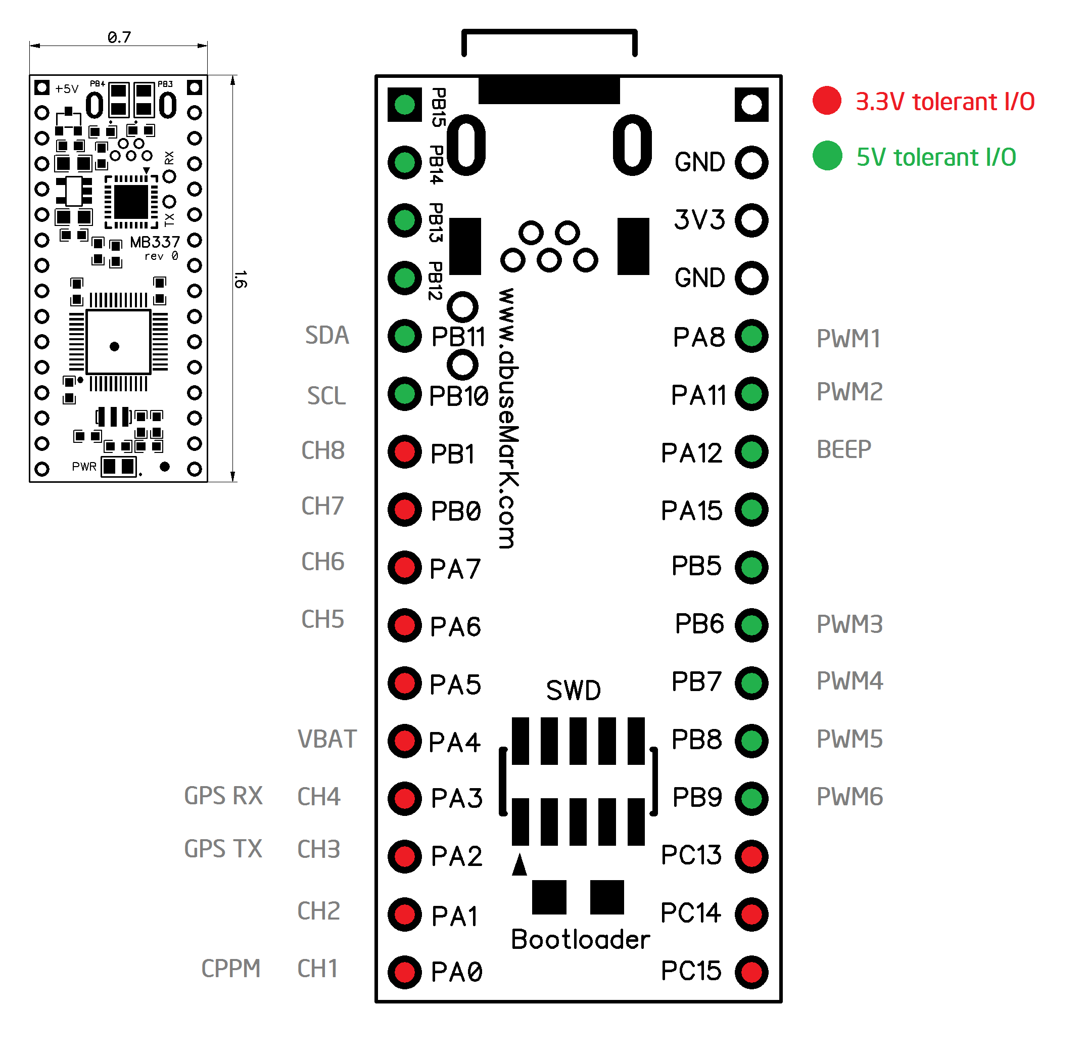
My personal plans are to use this with an PPM receiver (Deltang RX31). This is already working in the AVR328 based micro quad I referenced more early in this tread. Should be connected to PA0. I may connect the receiver to see if this is actually also working. I need to change feature PPM as the default since restart is not working.


Reading the datasheet it’s also not recommended to drive a load with pins PC13, PC14, PC15. Only 3mA output for all 3 pins together. But the designers of the board have done this (but it works). Anyhow I also tried to disable LED’s completely but this also does not change my main problem. Reading the datasheet for and back but cannot see any additional interference with other pins yet which may cause this behavior.

In the meantime I also found out the STM Flash Loader demo will be also able to start the code directly after flashing if you check the related box.
Last edited by mj666 on Wed Jul 02, 2014 7:25 am, edited 3 times in total.

timecop
Posts: 1880
Joined: Fri Sep 02, 2011 4:48 pm

Re: CJMCU microquad board

Post by timecop »

Right. Many people don't realize that driving leds with PC13.14.15 is a bad idea. I don't know why :)
Unfortunately I don't have much idea for your flash fail problem.
I guess best bet is to get debugging going so you can see where it crashes after reboot.

mj666
Posts: 186
Joined: Wed Feb 12, 2014 12:02 pm

Re: CJMCU microquad board

Post by mj666 »

Just have received the schematics from the board vendor. There is nothing really new to see there and it confirms my findings. According to the board vendor there is really no firmware for this yet and it looks not to be build for one of the existing open source projects. Interestingly there is the connector P8 which is prepared for the direct connection of an NRF24L01 wireless module as an receiver. I really have no idea how they could sell this and how much they already have sold during the last years. Anyhow I'm still waiting for my Discovery F4 to get debug working and will be confident we have a working firmware base on Baseflight soon.

@timecop how would you like to see changes for this CJMCU board to be applied for Baseflight. For now I have a very much stripped down version of Baseflight to get it to work initially. I finally can apply changes with conditional compilation? This may also include to make many sensors an option during build process. Looking forward to your feedback and thanks for your support.
Attachments
CJMCU.zip
(128.71 KiB) Downloaded 919 times
Last edited by mj666 on Tue Jul 08, 2014 12:36 pm, edited 3 times in total.

timecop
Posts: 1880
Joined: Fri Sep 02, 2011 4:48 pm

Re: CJMCU microquad board

Post by timecop »

Can you post schematic? I can try to add it as another brushed target, sure.

mj666
Posts: 186
Joined: Wed Feb 12, 2014 12:02 pm

Re: CJMCU microquad board

Post by mj666 »

Updated my previous post with more information including schematics.

timecop
Posts: 1880
Joined: Fri Sep 02, 2011 4:48 pm

Re: CJMCU microquad board

Post by timecop »

I committed some stuff, mainly rearranging board.h to add new target and minimize drivers/etc inclusion in Makefile.
As a side effect, this probably doesn't build at all - try it out and see how much effort it would be to make it build.
PPM maps are correct (I think). I also enabled brushed PWM by default on CJMCU target, as well as FEATURE_PPM. In my hardwareMaps, PPM is on PA0 (their schematic wants it elsewhere, but let's not do that).

mj666
Posts: 186
Joined: Wed Feb 12, 2014 12:02 pm

Re: CJMCU microquad board

Post by mj666 »

Started to work on this.

The makefile is missing a backslash at two places behind "$(HIGHEND_SRC)" line to work.

As you already stated the code will not compile for CJMCU and OLIMEXINO targets. I see following possibilities to proceed making the sensors drivers and other parts more configurable:

Option 1: same as you did for GPS with a define in boards.h
Option 2: do the define in the driver header file and if the related .h and .c file not included in the build the define is not present and related code in the remaining files will not be compiled.

Please let me know your preference.

mj666
Posts: 186
Joined: Wed Feb 12, 2014 12:02 pm

Re: CJMCU microquad board

Post by mj666 »

Have worked on the code to be able to compile without errors. The new code is working on initial flash but not after an restart. So behavior does not have been changed.

I also found out the order of motors needs to be adjusted to match the Baseflight standard order:

Code: Select all

CJMCU      BASEFLIGHT
1 PB8      4
2 PB9      2
3 PB0      1
4 PB1      3

I guess i still need to get the debugger up and running. I added the patch file for the changes i have done.
Attachments
baseflight.zip
(2.63 KiB) Downloaded 579 times
Last edited by mj666 on Wed Jul 09, 2014 12:44 am, edited 3 times in total.

timecop
Posts: 1880
Joined: Fri Sep 02, 2011 4:48 pm

Re: CJMCU microquad board

Post by timecop »

I think the 2nd option is probably better, but I'd have to see how it works. I don't wanna have multiwii-level sea of defines, either :)

dominicclifton
Posts: 202
Joined: Tue Feb 05, 2013 10:28 pm

Re: CJMCU microquad board

Post by dominicclifton »

timecop, why suddenly the rush to support non-naze hardware? I though you were against that what with your vested interest in selling Naze boards?

timecop
Posts: 1880
Joined: Fri Sep 02, 2011 4:48 pm

Re: CJMCU microquad board

Post by timecop »

mj666 wrote:I guess i still need to get the debugger up and running. I added the patch file for the changes i have done.


thanks, merged what was possible.
you missed a 4-space tab in the patch -> all tabs must be converted to spaces.
also I redid inverter stuff as #define INVERTER and test is same as LEDx, to make it slightly more consistent.
so these changes make everything build for CJMCU?

mj666
Posts: 186
Joined: Wed Feb 12, 2014 12:02 pm

Re: CJMCU microquad board

Post by mj666 »

I have updated my local repository. There are still some changes in the makefile required to build properly (MAG driver is needed and I did not remove ADC code since its more complicated and will not really hurt). Also have undone the calculation for the EEPROM location. The actual code for CJMCU target is now below the 64kb but this will conflict if building other targets with GNU toolchain and load them to a STM32F103C8T6. The patch is added below (have fixed my settings for the Tab configuration ;) ). I also have test build all other targets successfully.

BTW: The actual code is running for hours and communicating with the GUI if the board did not get restarted or power toggled.
Attachments
baseflight.zip
(638 Bytes) Downloaded 550 times

timecop
Posts: 1880
Joined: Fri Sep 02, 2011 4:48 pm

Re: CJMCU microquad board

Post by timecop »

OK, I got rid of flash size register shit as it seems to be useless anyway as your C8 still has 128k flash.
Also fixed makefile to include compass driver and added -CJMCU target to keil workspace - and made sure it builds.

mj666
Posts: 186
Joined: Wed Feb 12, 2014 12:02 pm

Re: CJMCU microquad board

Post by mj666 »

@timecop thanks for the update. Unfortunately I still wait for my Discovery F4 for debugging. The store will now send a replacement since the first on looks to be get lost. In the time till the board arrives I'm focusing on my other Nanocopters specifically Hexa and Octocopter the will be driven by an AfroMini32. In addition I need motor controllers and the receiver. All components are really tiny and challenging to put together. For the Octocopter I even need to solder 2 wires to the STM32 directly to get the motor 7 and 8 signals.

viewtopic.php?f=12&p=53226#p53226

BTW: What about a project for Naze32 Brushed with 8 brushed motor controllers (3,5 dual FET or 6A single FET) and an integrated receiver (Deltang is selling already programmed controllers for DSM2/DSMX). This will cover many mini/nano quadcopter needs. ;)

Edit: I think in the makefile the drv_adc.c for CJMCU target is still missing to compile properly?

mj666
Posts: 186
Joined: Wed Feb 12, 2014 12:02 pm

Re: CJMCU microquad board

Post by mj666 »

Today my Discovery F4 board finally arrived. I hooked it up and configuration was running seamless. What I actually can see the STM32 will immediately get an exception and will end up either in Reset_Handler(), HardFault_ Handler() or in the boot loader area around address 0x1ffff020. An breakpoint at the beginning of the main function will never be reached.

mj666
Posts: 186
Joined: Wed Feb 12, 2014 12:02 pm

Re: CJMCU microquad board

Post by mj666 »

Till now I was not very successful finding the problem. First I found out OOCD is only flashing the first 64kb of the STM controller only. And the code was trying to call functions in the unflashed area. Changing the following line to the stm32f1x_stlink.cfg configfile fixed this problem:

Code: Select all

flash bank $_FLASHNAME stm32f1x 0 0 0 0 $_TARGETNAME

to

Code: Select all

flash bank $_FLASHNAME stm32f1x 0 0x20000 0 0 $_TARGETNAME

The code (debug and nondebug builds) is still running ones after initial flash with STM Demo Loader but not if started from the debugger. At the moment it looks to be some variables inside the "pwm_params" structure will be destroyed during execution of the pwminit() function. This structure is referenced via the "init" pointer inside the pwmInit() function. Finally this will cause an exception and end up in the HardFault_ Handler(). I only can see it after the return of the following line the structure content is messed up;

Code: Select all

            motors[numMotors++] = pwmOutConfig(port, mhz, hz / init->motorPwmRate, init->idlePulse);

This will happen during each call in the loop but different variables are affected. Unfortunately I have not found out how I can continuously monitor this structure during execution of other functions in the debugger. Stepping true PWMOutConfig() function and subfunctions the reference to "pwm_params" or "init" will be invalid.

timecop
Posts: 1880
Joined: Fri Sep 02, 2011 4:48 pm

Re: CJMCU microquad board

Post by timecop »

mj666, pluschi brought to my attention the reason why your board might not be "booting" on next reboot after flashing firwmare.
according to schematic you posted, BOO0 pin is permanently tied to VCC (via R12), which permanently sticks it in bootloader mode.
So when you flash it, and "run", it works, but next reboot goes right back to bootloader.
Ther'es a boot0 pad on top of the board between stm32 and mpu6050. put a solder jumper on it to fix this.

mj666
Posts: 186
Joined: Wed Feb 12, 2014 12:02 pm

Re: CJMCU microquad board

Post by mj666 »

Thanks plüschi and timecop. This really was the problem. Not sure why in did not even think about it (the pins are labeled with boot0 and not boot1). I still don’t understand why I didn’t get permanently into boot loader mode without shorting the pins. Definitely it makes now sense that sometimes if I short the boot pins the firmware was started. I connected an receiver already and everything locks good now. I will finalize the Quad with motors and see if I can get it to fly. Thanks again to both of you.
Last edited by mj666 on Sun Jul 27, 2014 8:08 pm, edited 2 times in total.

User avatar
Plüschi
Posts: 433
Joined: Thu Feb 21, 2013 6:09 am

Re: CJMCU microquad board

Post by Plüschi »

Mj666 can you post your files / changes you made?
I cant run latest baseflight with target=cjmcu, it will do nothing at all.
But i can run a simple LED test program.

mj666
Posts: 186
Joined: Wed Feb 12, 2014 12:02 pm

Re: CJMCU microquad board

Post by mj666 »

Hello all the CJMCU had maiden flight some minutes ago. For me it works with the latest Baseflight master with no additional changes. I compile with actual GNU ARM toolchain. Attached you can find the working HEX file. I use the flowing settings in the CLI.

mixer QUADX
feature PPM
feature FAILSAFE
map TAER1234
set minthrottle = 1000
set maxthrottle = 2000
set failsafe_throttle = 1350
set motor_pwm_rate = 32000
set align_mag = 3
set mag_declination = 154

Everything else is actually stock. Have not finaly tested mag orientation and function yet. There is a light wobble and it's really agile. Actually I only tried in the garden with not much space.

Thanks for everybodys help.
Attachments
baseflight_CJMCU.zip
(57.34 KiB) Downloaded 656 times
CJMCU1.jpg
CJMCU2.jpg
Last edited by mj666 on Wed Jul 30, 2014 11:42 pm, edited 2 times in total.

User avatar
Plüschi
Posts: 433
Joined: Thu Feb 21, 2013 6:09 am

Re: CJMCU microquad board

Post by Plüschi »

I confirm your .hex works. With ppmsum, it doesent work with serialrx. Would be nice to have speksat added.

Unluckily i'm not able to compile that thing to a small enough size....

mj666
Posts: 186
Joined: Wed Feb 12, 2014 12:02 pm

Re: CJMCU microquad board

Post by mj666 »

There are only unused sensors, softserial, gps. etc. removed for the CJMCU target. The different receiver protocols should work like in standard NAZE target. Anyhow the CJMCU does also have 128 Kb flash memory and this should not be a limitation. The actual CJMCU HEX is still smaller than 64kb?

User avatar
Plüschi
Posts: 433
Joined: Thu Feb 21, 2013 6:09 am

Re: CJMCU microquad board

Post by Plüschi »

serialrx is disabled in mw.c

Code: Select all

#ifndef CJMCU
    // calculate rc stuff from serial-based receivers (spek/sbus)
    if (feature(FEATURE_SERIALRX)) {


I think your hex is 52k. Mine is 72k all unused modules removed. I use the "ARM Sourcery Windows GNU" which might be the cause.

timecop
Posts: 1880
Joined: Fri Sep 02, 2011 4:48 pm

Re: CJMCU microquad board

Post by timecop »

Don't use that.
The only supported toolchain is gcc-arm-embedded from launchpad ( https://launchpad.net/gcc-arm-embedded )

User avatar
Plüschi
Posts: 433
Joined: Thu Feb 21, 2013 6:09 am

Re: CJMCU microquad board

Post by Plüschi »

I did install that already. But i have no clue how to make eclipse actually use it instead of the sourcery stuff.

Edit:
OK, i did manage to compile that. Now, why does serialrx not work?

Post Reply