Spare-Parts TriCopter Build MWP2

Post Reply
User avatar
SkySpaghetti
Posts: 34
Joined: Wed Sep 30, 2015 7:43 am

Spare-Parts TriCopter Build MWP2

Post by SkySpaghetti »

I had a bunch of bits laying around so I figured I'd try and put together a TriCopter. I've built Quads and Hex's but never a TriCopter. I'll do my best to keep this build-thread up to date with as many details and photos as I go.

I know I'll need a lot of input on setting up the Multiwii system as I've only had a little experience with Multiwii on an old Quadrino board I used a long time ago. So any comments, tips or tricks are always welcome!

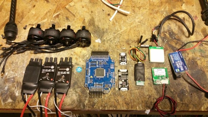
Here's some of the spare parts I have that I'll be using for the build:
    - Multiwii Pro 2.0 board (from ReadyToFlyQuads.com)
    - Bluetooth Adapter (FTB06 v2)
    - MinimOSD (Cuav)
    - GPS Receiver (R-15e)
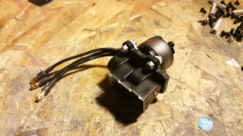
    - Team BlackSheep 30a ESCs
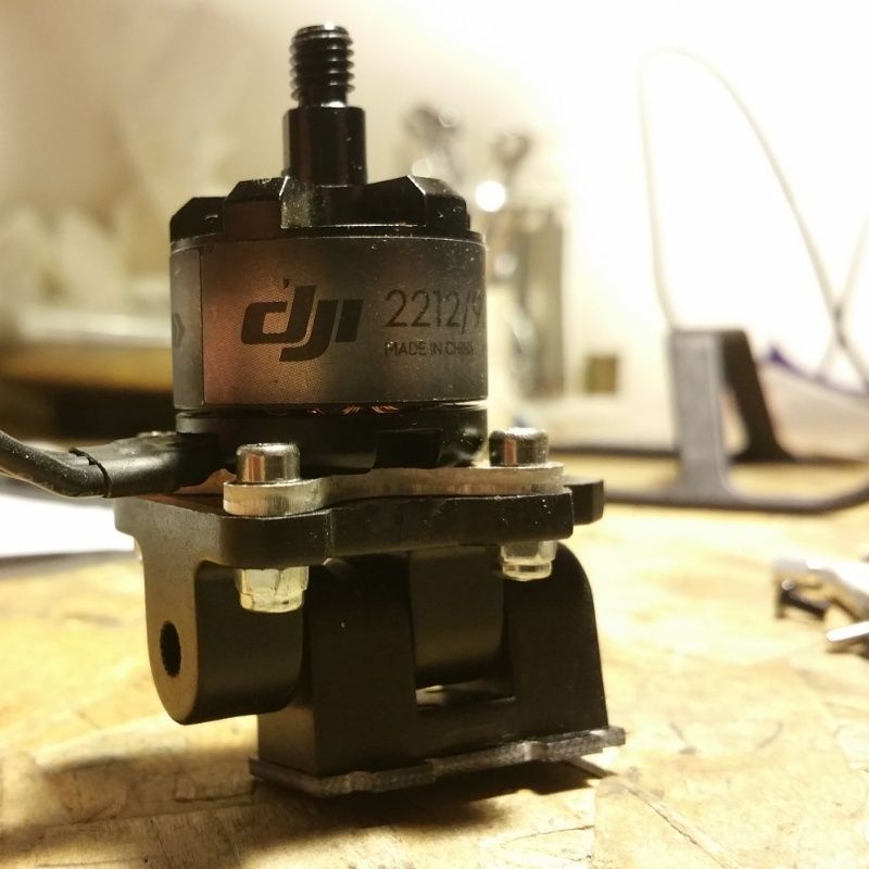
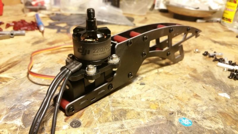
    - DJI 2212/920 Motors

Image

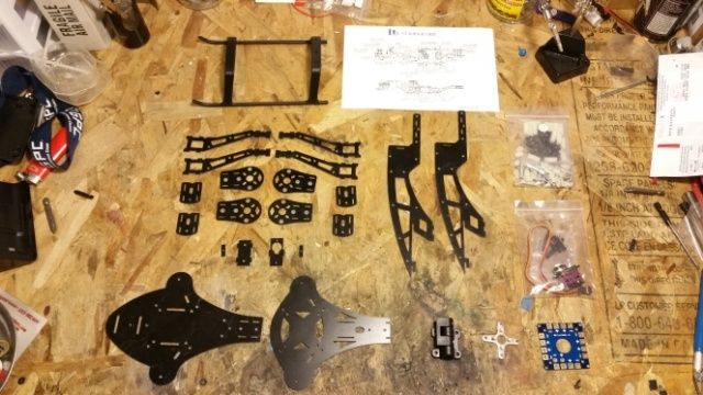
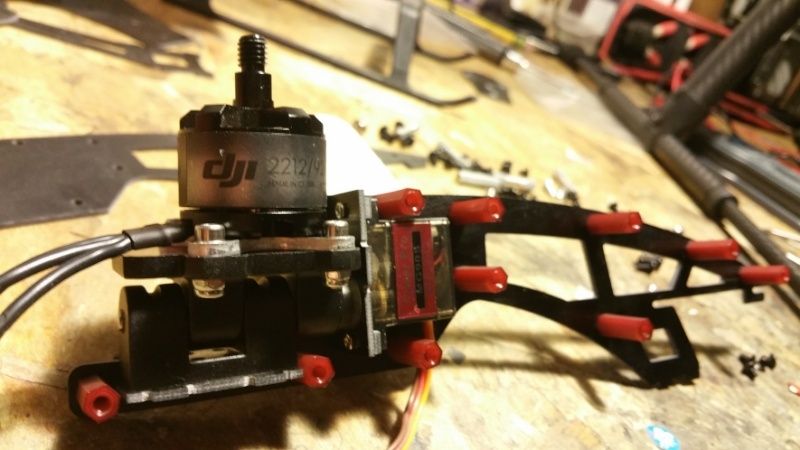
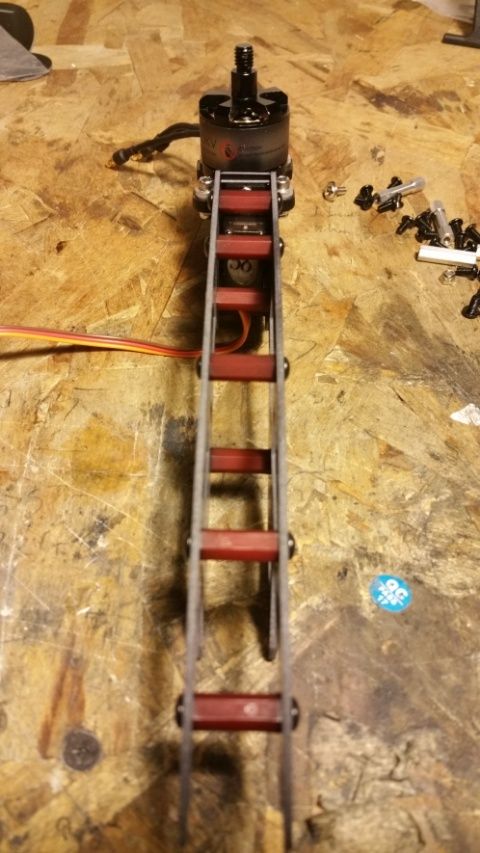
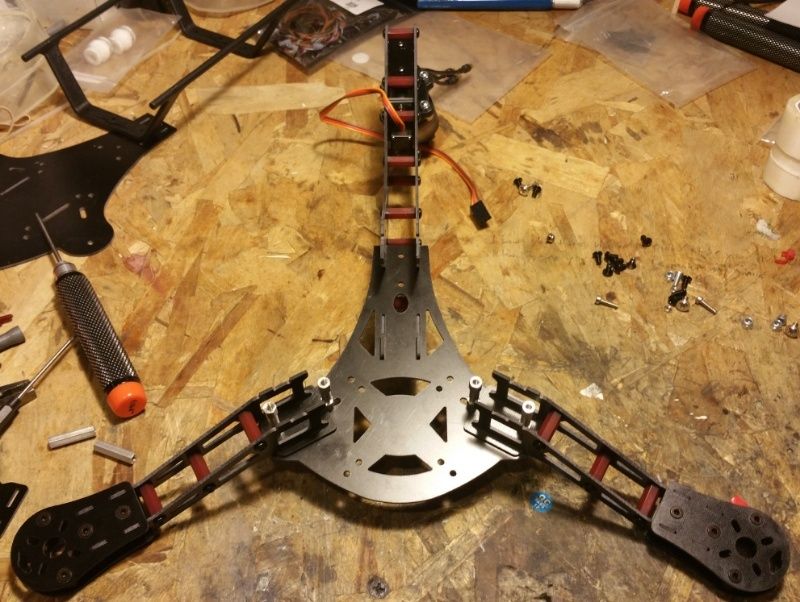
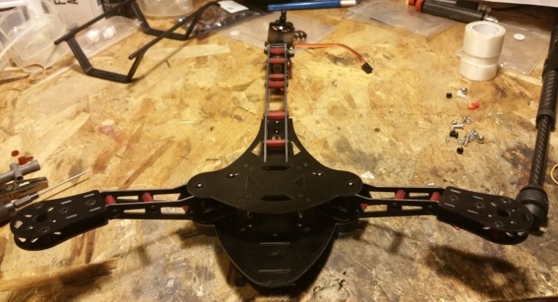
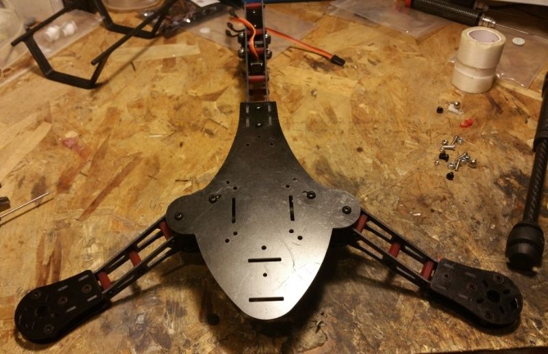
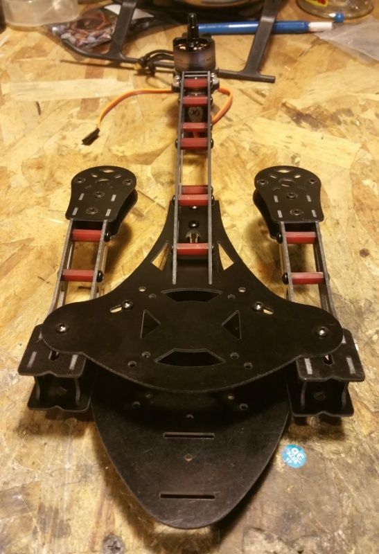
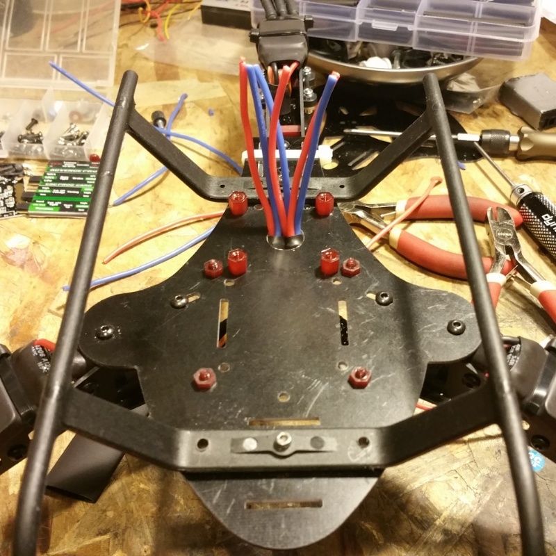
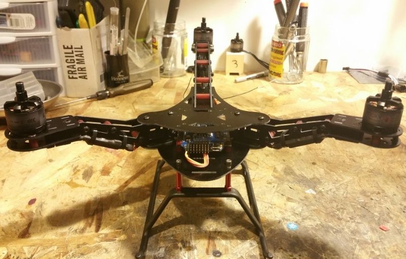
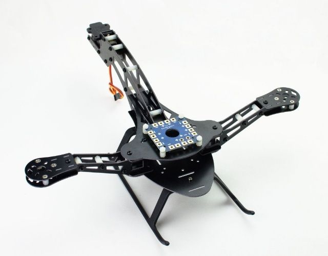
The below pic is the frame I purchased off Ebay. I liked the size and portability of this frame. Plus it was fairly cheap.

Image

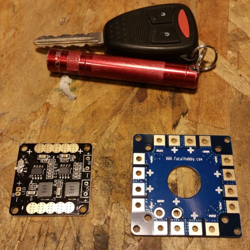
I also ordered a mini PDB with LED power switch and built in BECs and an FTDI adapter from ReadyToFlyQuads.com.

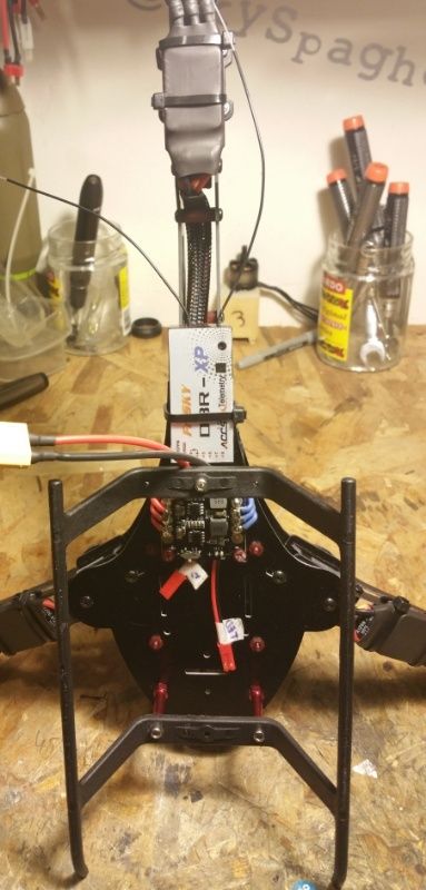
I'm planning to control everything with my Turnigy 9X Tx and a D8R-XP Rx. I'd like to set up the RX using PPM if possible on the Multiwii Pro.

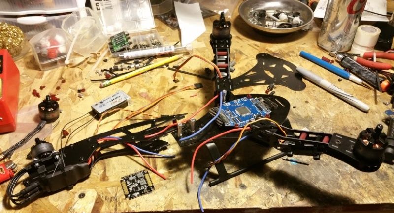
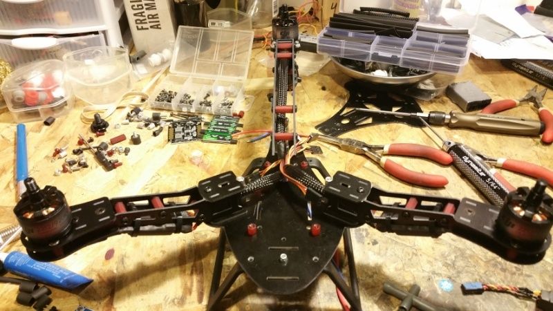
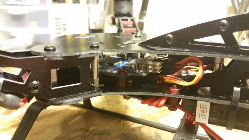
One trick I'll probably try is orienting the Multiwii board lengthwise in the frame. This will require me to change the orientation of the sensors 90degrees. I know there are already options for 45degree offsets in the Config file, but I'm not sure about a full 90.

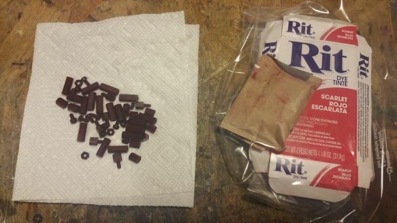
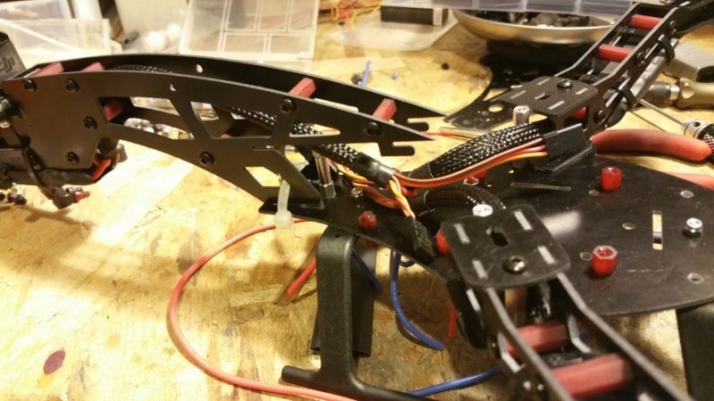
I'm thinking I might also try dying the frame spacers a different color to trick it out a bit. I'll take a trip to the local craft store for some Rit Dye in the next day or so.

edsimmons3
Posts: 100
Joined: Thu Sep 10, 2015 11:29 am

Re: Spare-Parts TriCopter Build MWP2

Post by edsimmons3 »

Looks very cool...

If you ever plan to use GPS navigation, heading hold or headfree modes, get that power distribution board as far away as possible from the flight controller. The magnetic fields around the PCB power distribution boards are strong and will mess up magnetometer heading really easily! Just my 2p! If you can't get the distance needed, mumetal screening is the way forwards.

Hope that helps...
Ed

User avatar
SkySpaghetti
Posts: 34
Joined: Wed Sep 30, 2015 7:43 am

Spare-Parts TriCopter Build MWP2

Post by SkySpaghetti »

The frame came in today. Looks pretty good. For under $30 it comes with a PDB, Landing Gear and Tail Servo. It's a little smaller than I anticipated but it'll still work. Just might take a bit more tweaking!

Image

User avatar
SkySpaghetti
Posts: 34
Joined: Wed Sep 30, 2015 7:43 am

Spare-Parts TriCopter Build MWP2

Post by SkySpaghetti »

edsimmons3 wrote:Looks very cool...

If you ever plan to use GPS navigation, heading hold or headfree modes, get that power distribution board as far away as possible from the flight controller. The magnetic fields around the PCB power distribution boards are strong and will mess up magnetometer heading really easily! Just my 2p! If you can't get the distance needed, mumetal screening is the way forwards.

Hope that helps...
Ed

Thanks Ed. I figured as much. I was thinking of mounting the GPS on the tail in front of the rear motor but I'm not sure if the spinning prop would affect reception. Once I have everything mocked up and I can tell how much blade clearance I have, I'll probably mount the GPS on a pole above the craft like most multirotors do.

I'm going to try and keep the ESCs and PDB mounted under the frame as upposed to out on the arms. (I like to keep my builds as clean as possible) This might require some custom brackets to make space between the bottom plate and landing gear tho.

User avatar
SkySpaghetti
Posts: 34
Joined: Wed Sep 30, 2015 7:43 am

Post by SkySpaghetti »

I attempted to Rit Dye the nylon spacers and nuts today... it definitely worked, though a bit too well. Not quite the "Red" I was hoping for...

Image

I'll roll with it for now. Maybe just go all black if it's an eyesore.

User avatar
SkySpaghetti
Posts: 34
Joined: Wed Sep 30, 2015 7:43 am

Post by SkySpaghetti »

New PDB from ReadyToFlyQuads.com came in today.
Image

Bit of a size difference from the one that came with the kit. Especially considering it has 2 BECs and a dedicated switch and output for LEDs.

Not quite sure where the rest of the order is though... they must've expedited the packages.

User avatar
SkySpaghetti
Posts: 34
Joined: Wed Sep 30, 2015 7:43 am

Spare-Parts TriCopter Build MWP2

Post by SkySpaghetti »

The rest of the parts finally came in today. I got some additional spacers, the X8R-XP Rx, an FTDI adapter, a protective cover for the Multiwii and a few other doo-dads...

Should be able to start assembling the frame and getting everything wired up this week.

Does anyone have a good reference for the CONFIG settings to rotate the Multiwii 90° Clockwise in the frame?

That's going to be the tricky part of this build.

Thanks!

User avatar
SkySpaghetti
Posts: 34
Joined: Wed Sep 30, 2015 7:43 am

Spare-Parts TriCopter Build MWP2

Post by SkySpaghetti »

Finally got the build going. I started with the tail piece as it looks like the top and bottom frame plates interlock with the tail.

The YAW servo screws into a plate that gets sandwiched between the rails of the tail.

Image

The YAW mechanism for the rear motor is quite simple but fairly solid. The motor mounts to the top of a hinge that has one end notched out to mate with the servo horn.

Image

Image

I've seen other setups that use linkages and have bearing and whatnot, I'm sure they're a bit more efficient and use larger setups, but I'd think this type of YAW assembly would take more of a beating.

The YAW Motor assembly and servo both sandwich between the Tail Piece rails and are locked into place by tabs on the motor and servo mounts and precut grooves on the rails.

Image

Image

Image

The Rit Dyed Spacers ended up not looking so bad after all. I was worried they'd be too dark, but I soaked them in some Rit Dye Color Remover solution and it helped lighten them up a tad.

Next up will be assembling the front arms and mocking up all the components on the frame.

User avatar
SkySpaghetti
Posts: 34
Joined: Wed Sep 30, 2015 7:43 am

Post by SkySpaghetti »

Mocked up the frame. This is definitely a decent looking kit. Hope it flies as good as it looks...

Here's the frame minus the top plate. I'm planning to mount the Multiwii in between the two plates for extre protection.

Image

Frame assembled.

Image

Bottom plate. Still need to install the landing gear.

Image

Arms folded for travel.

Image

User avatar
SkySpaghetti
Posts: 34
Joined: Wed Sep 30, 2015 7:43 am

Post by SkySpaghetti »

ESCs and Motors are installed and I'm getting everything wired up. I ended up having to go with some old 20a Turnigy ESCs I had laying around as the Team BlackSheep ESCs were too long to fit neatly on the arms or under the frame.

Image

Image

Image

Most people mount the FC on the top plate and the PDB in the middle. I wanted to mount the FC between the top and bottom frame plates for protection and also so I can mount the GPS and Bluetooth modules on the top plate.

To do this I drilled a hole in the bottom plate and ran the ESC power leads thru it.

Image

I then mounted the Combo PDB/BEC Board on the bottom using standoffs. I also used standoffs to extend the landing gear.

Image

Once I get the system worked out, I'll also mount the VTX under the bottom plate in front of the PDB and use an SMA extension cable to mount the antenna on the top of the craft. For now though everything fits nice and neat.

Image

Image

I have the RX running on PPM and the ESCs on the D6,5, and 3 pins. The 5v BEC off the PDB powers the system on the 5 pin's power terminals. I have the servo on pin D2 but I'm having issues getting the servo to function.

In the GUI everything looks to be working properly, but when I power on the craft, I can get the motors to arm and power up but there's no reaction on the YAW Servo.

This happens in MW2.3.
When I try MW2.4 I can't even get the motors to arm.

I have another thread going to tryand solve this, but any input is much appreciated.

User avatar
SkySpaghetti
Posts: 34
Joined: Wed Sep 30, 2015 7:43 am

Post by SkySpaghetti »

Still not having any luck with the YAW Servo. I can't seem to find which pin outputs the signal. None of the recommended pins seem to work. I've also tried to comment out the HW_MEGA_SERVO settings but I'm still not getting anything... bah!

User avatar
SkySpaghetti
Posts: 34
Joined: Wed Sep 30, 2015 7:43 am

Post by SkySpaghetti »

So, it turns out the Multiwii Mega Pro 2 board I'm using doesn't output power for the Yaw Servo on the D2 Pin.... you think that would be documented somewhere that's easy to find... :-/

Anyway, I was able to splice a 2nd 5v power line from my PDB to my servo and just run the Signal Wire off the board and BAM... Yaw Servo is working!!

Unfortunately, somewhere along the way I may have fried my Serial 1 Port as my PPM is no longer working. I'm able to run analog to the board though, so for now I'll just get everything up and running and I'll worry about the PPM later.

Post Reply