Re: Alternative ESC firmware (reflashing)
Posted: Wed Oct 26, 2011 5:44 pm
Hi, Heiko!
I didn't realize you saw problems even with slow throttle increases. Does this also happen with my tree? I thought it was only a fast response change problem. This is with a 14" APC prop?
It's possible that the motor is just saturating due to too much current. It's rated for 14.5A and 200W according to http://www.rctigermotor.com/show.php?contentid=142 , and you are seeing the problem start at around 16A @ 16V (256W). I wish there was some simple way to collect a full high speed log of the whole drive and zero-crossing detection, like a 4-channel oscilloscope with long buffer. Hmm, perhaps it would work to trigger the scope from one of the unused pins when commutation loss is detected? At least then we could look at what is happening right around when it failed, on a digital scope.
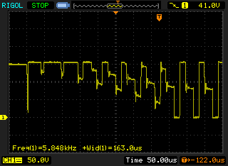
Those scope pictures I posted were not from full load, but if you look at a shorter timescale, the noise patterns change as the motor current increases. The kick-back takes longer to demagnetize and so this affects the noise at the comparator -- the swing back to high stays high longer until the current stops and the undriven phase sees just backEMF. It's almost like a current sense by pulse length. The high part stays high longer based on current, while the lower part is just the length of the PWM ON cycle (and this is proportional to drive voltage). This scope screenshot is just one phase, not at the comparator which has the neutral subtracted, but if you imagine noise each time the signal changes, you can see how picking up a valid zero-crossing can be difficult: http://0x.ca/sim/tmp/motor_phase_zoom.png
If the motor saturates, I would expect the current to start spiking excessively at the end of the PWM ON cycle. I'm not quite sure what would happen next, however.
Cheers,
Simon-
I didn't realize you saw problems even with slow throttle increases. Does this also happen with my tree? I thought it was only a fast response change problem. This is with a 14" APC prop?
It's possible that the motor is just saturating due to too much current. It's rated for 14.5A and 200W according to http://www.rctigermotor.com/show.php?contentid=142 , and you are seeing the problem start at around 16A @ 16V (256W). I wish there was some simple way to collect a full high speed log of the whole drive and zero-crossing detection, like a 4-channel oscilloscope with long buffer. Hmm, perhaps it would work to trigger the scope from one of the unused pins when commutation loss is detected? At least then we could look at what is happening right around when it failed, on a digital scope.
Those scope pictures I posted were not from full load, but if you look at a shorter timescale, the noise patterns change as the motor current increases. The kick-back takes longer to demagnetize and so this affects the noise at the comparator -- the swing back to high stays high longer until the current stops and the undriven phase sees just backEMF. It's almost like a current sense by pulse length. The high part stays high longer based on current, while the lower part is just the length of the PWM ON cycle (and this is proportional to drive voltage). This scope screenshot is just one phase, not at the comparator which has the neutral subtracted, but if you imagine noise each time the signal changes, you can see how picking up a valid zero-crossing can be difficult: http://0x.ca/sim/tmp/motor_phase_zoom.png
If the motor saturates, I would expect the current to start spiking excessively at the end of the PWM ON cycle. I'm not quite sure what would happen next, however.
Cheers,
Simon-