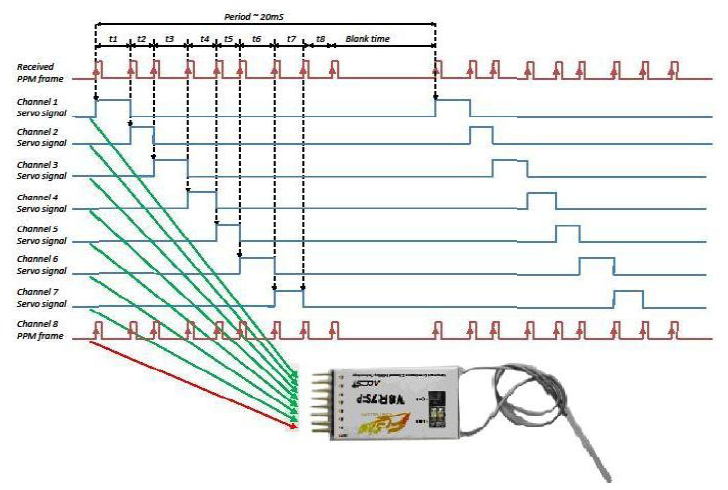
The circuit consists only of an atMega328 chip with a simple 20 line program. Chip is running using internal oscillator at 8mhz. I added the FTDI header so I can reprogram if needed and also serves as servo connector to FC PPM input. You can buy atmega328 on ebay for $3.33.
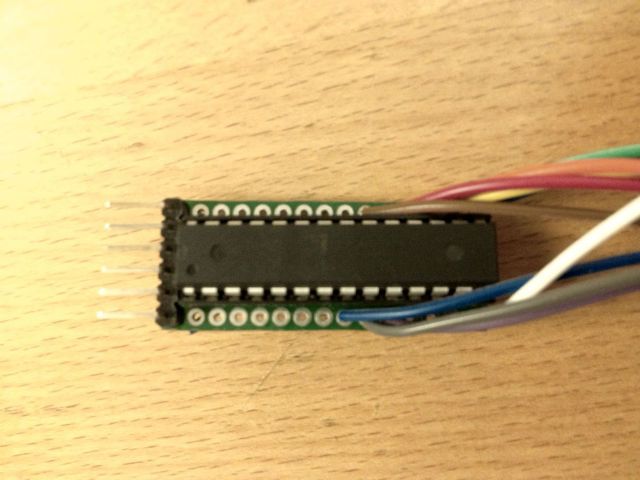
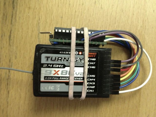
The atmega328 chip/prototype board attaches to the side of the RX
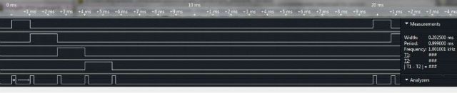
This is the logic analyzer capture for 4 channels. I used a pulse width of 300us (this screen shot still shows 200us)
Works great. Now I have 5 extra pins on my FC.
This is the program. 20 lines long not counting comments. Compiles to 566 bytes.
Code: Select all
#define PPMHI PORTD |= _BV(7);
#define PPMLO PORTD &= ~_BV(7);
//written by doughboy @RCGroups and @multiwii.com
//8 channel Serial Sum PPM using atmega328 minimal circuit running on 8mhz internal oscillator
//wiring
//connect RX pins 0-7 to atmega PortB pins 0-7, chip pins 14 to 19, 10 and 11
//ppm output on digital pin 7, atmega chip pin 13
//                  +-\/-+
//            PC6  1|    |28  PC5
//            PD0  2|    |27  PC4
//            PD1  3|    |26  PC3
//            PD2  4|    |25  PC2
//            PD3  5|    |24  PC1
//            PD4  6|    |23  PC0
//      +5v-> VCC  7|    |22  GND  <-Gnd
//      Gnd-> GND  8|    |21  AREF
//      RX6-> PB6  9|    |20  AVCC <-+5v
//      RX7-> PB7 10|    |19  PB5 <-RX5
//            PD5 11|    |18  PB4 <-RX4
//            PD6 12|    |17  PB3 <-RX3
//   PPMSUM<- PD7 13|    |16  PB2 <-RX2
//      RX0-> PB0 14|    |15  PB1 <-RX1
//                  +----+
//
//this code will run only on minimal 8mhz atmega328.
//you must modify the code and move PB6 and PB7 to another port if you use a setup with oscillator

void setup() {
  PCICR |= (1<<PCIE0); //Pin Change Interrupt 0
  PCMSK0 = 0xFF; //all 8 pins
  TCCR2A = 0;
  TCCR2B |= (1<<CS22) | (1<<CS20); //div 128 prescaler
  TIMSK2 |=(1<<OCIE2B);
  DDRD |= _BV(7);  //digital pin 7 output
}

void loop() {
}

ISR(PCINT0_vect) {
    PPMHI;
    TCNT2=0;
    OCR2B=19; //300us PPM pulse
}

ISR(TIMER2_COMPB_vect) {
  PPMLO;
}